2025 Transfer Seatpost Owner's Guide
For instructions to help you decide which length Transfer Seatpost will best fit your application, please click: Determine Which 2025 Transfer Seatpost Will Fit Your Bike »
WARNING: FOX products should be installed by a qualified bicycle service technician, in accordance with FOX installation specifications. If you have any doubts as to whether or not you can properly install the Transfer adjustable height seatpost on your bicycle, defer to a professionally trained bicycle service technician. Improperly installed products can fail, causing the rider to lose control, resulting in SERIOUS INJURY OR DEATH.
WARNING: Regardless of bicycle frame tube configuration, the best structural support is achieved when the Transfer seatpost is inserted at least to 1) the minimum insertion mark on the seatpost, AND 2) the minimum insertion point specified by the manufacturer of your bicycle frame. Neglecting these two items risks causing damage to the frame and seatpost, resulting in SERIOUS INJURY OR DEATH.
WARNING: Make sure that the Transfer remote lever does not interfere with normal brake and shift lever operation. Failure to do so can result in loss of control, resulting in SERIOUS INJURY OR DEATH.
WARNING: Make sure that the bottom cap of the Transfer seatpost never touches any part of the frame, or the rear shock through the entire range of shock travel. Make sure that no part of the internal actuation mechanism at the base of the seatpost contacts any internal seat tube parts such as frame pivots or bottom bracket parts. Failure to do this risks causing damage to the frame and seatpost, resulting in SERIOUS INJURY OR DEATH.
WARNING: Make sure your seatpost is the correct outer diameter to fit your bicycle seat tube inner diameter. Using the incorrect size of the Transfer seatpost on your bicycle can lead to product damage, personal injury, or both.
WARNING: Make sure the cable housing does not interfere with the swingarm linkage, rear tire, clothing and riding gear, and steering clearance. Never attach the cable housing to any part of your rear shock.
WARNING: The anodized surface of the upper seatpost, like a rear shock body, serves as a sealing surface. Always take every precaution to avoid causing abrasion damage to the anodized surface of the upper seatpost. The upper portion of the Transfer seatpost may be carefully clamped in a workstand. Do not clamp the cable pulley mechanism of collar cable routed Transfer seatposts.
Remote Installation
1X REMOTE LEVER INSTALLATION (22.2 CLAMP)
- Install the remote lever clamp onto the handlebar in the desired location. Make sure to keep clearance between the remote lever and any brake or shifter controls.
-
Insert the bolt through both sides of the clamp. Then use a 4 mm hex wrench to turn the bolt clockwise and tighten to 17.7 in-lb (2.0 Nm). Less torque may be needed for carbon bars. Refer to the handlebar manufacturer’s instructions for use with carbon bars.

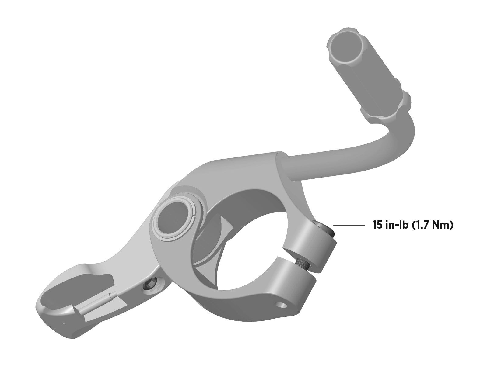
2X/3X REMOTE LEVER INSTALLATION (22.2 CLAMP)
- Install the remote lever clamp onto the handlebar in the desired location. Make sure to keep clearance between the remote lever and any brake or shifter controls.
-
Insert the bolt into the clamp as shown. Then use a 2.5 mm hex wrench to turn the bolt clockwise and tighten to 15 in-lb (1.7 Nm). Less torque may be needed for carbon bars. Refer to the handlebar manufacturer’s instructions for use with carbon bars.
1X REMOTE LEVER INSTALLATION (COMPATIBLE WITH MATCHMAKER INTERFACE)
- Install and position the brake lever according to the brake manufacturer’s instructions.
-
Install the remote lever onto the brake lever clamp using the adapter and mounting bolt supplied by the brake manufacturer. Tighten to 17.7 in-lb (2.0 Nm). Make sure to keep clearance between the remote lever and any brake or shifter controls. NOTE: Only one of the bolt holes will be utilized during installation, according to your setup needs.

1X REMOTE LEVER INSTALLATION (I-SPEC EV)
- Install and position the brake lever according to the brake manufacturer’s instructions. Make sure to install the supplied nut into the band clamp of the brake lever during this step.
-
Install the remote lever and adapter to the brake lever clamp using the supplied mounting bolts. Tighten both bolts to 17.7 in-lb (2.0 Nm). Make sure to keep clearance between the remote lever and any brake or shifter controls.

Internal Cable Routing
- Route the cable housing from the remote lever into the internal routing port of the frame. Push the housing through the frame until the housing emerges from the seat tube and extends approximately 2 in (50 mm) beyond the seatpost clamp. Install a ferrule on the seatpost end of the cable housing.
- Install the cable bushing onto the cable. Seat the cable head into the counterbore of the cable bushing. Install the cable into the cable housing starting from the seatpost end.
- Seat the cable bushing into the actuation cradle at the bottom of the seatpost. Pull the cable at the lever end while pushing the cable housing into the frame to seat the housing against the cable stop at the base of the seatpost (see Figure 1).

- Note the correct seatpost orientation (see Figure 2). Insert the seatpost into the seat tube while pulling the cable from the internal routing port of the frame. Use friction paste for carbon frames, if needed. Tighten the seatpost clamp bolt to set the seatpost to the desired height.

- Determine how much cable housing is needed between the lever and the internal routing port of the frame. Make sure to allow enough slack for proper steering clearance. Mark the housing where you intend to cut, but do not cut it yet.
- Remove the seatpost and cable from the seat tube, leaving approximately 2 in (50 mm) of housing beyond the seatpost clamp. Remove the cable bushing from the actuation cradle. Remove the cable from the cable housing.
- Cut the cable housing at the mark. Install a ferrule onto the cable housing at the lever end. Lightly lubricate the cable and install it into the cable housing starting from the seatpost end.
- Seat the cable bushing into the actuation cradle at the bottom of the seatpost. Pull the cable at the lever end while pushing the cable housing into the frame to seat the housing against the cable stop at the base of the seatpost.
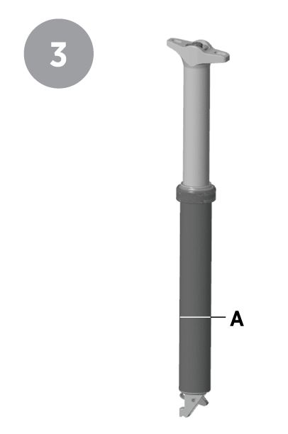
- Insert the seatpost into the seat tube while pulling the cable from the internal routing port of the frame (use friction paste for carbon frames if needed). Set the seatpost at the desired height. Make sure the “Minimum Insertion Line” on the seatpost (see Figure 3A) is inserted past the seatpost clamp of the seat tube. Check again that the seatpost properly moves into all positions. Tighten the seat tube clamp binder bolt to the torque range engraved on the lower post. NOTE: Excessive bolt tightness can adversely affect the action of the seatpost.
- Install the cable into the barrel adjuster of the lever until it exits past the clamp bolt. Ensure the barrel adjuster is turned completely clockwise. Pull the cable tight to seat each end of the housing. Hold the lever in the fully extended position while tightening the clamp bolt to the correct torque value shown for your lever (see Figure 4).
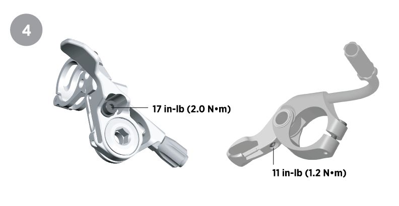
- Press the lever down completely 5-10 times. To remove any cable slack, loosen the pinch bolt and pull the cable, then hold the lever in the fully extended position while tightening the pinch bolt to the correct torque value shown for your lever (see Figure 4). Use the barrel adjuster to fine-tune the cable tension.
- Cut the cable to the correct length. Make sure to leave approximately 0.8 in (20 mm) visible at the remote end. Install the end crimp and tuck the end of the cable into the recess in the underside of the lever.
WARNING: Use the Transfer seatpost in a safe, controlled environment BEFORE using it during rides in order to fully understand how the seatpost functions. A sudden, unexpected impact from the saddle could cause you to lose control of your bicycle, resulting in SERIOUS INJURY OR DEATH.
Set the Air Pressure
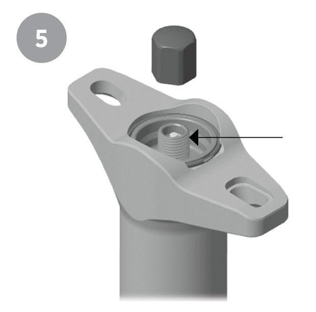
The Transfer seatpost is designed with an adjustable air valve under the saddle at the seatpost head. Air pressure changes with temperature in all suspension products. FOX recommends setting the air pressure with the seatpost at or near the temperature in which you’ll be riding. If you set your air pressure in warm conditions, it will be lower in cold temperatures and the seatpost will return slower.
- Remove the valve cap by hand or by holding onto a 10 mm socket. Use a FOX shock pump to set the air pressure of the seatpost between 275-325 psi (19-22 bar). (See Figure 5). Then reinstall the valve cap finger tight. NOTE: You can hold onto a 10 mm socket with your hand to tighten the valve cap, but do not tighten the valve cap with a socket wrench.
Install the Saddle
- Place the lower saddle clamp on the seatpost with the arrow on top facing the front of the bike (see the lower arrow in Figure 6).
- Insert the two nuts into the slots of the upper clamp (see Figure 6).
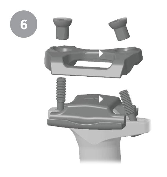
- Install the saddle on top of the lower clamp.
- While holding the nuts in place with your fingers, place the upper saddle clamp on top of the saddle rails with the arrow on top facing the front of the bike (see the upper arrow in Figure 6).
- While continuing to hold the nuts in place with your fingers, begin to install the two saddle clamp bolts. Install the saddle clamp bolts into the underside of the upper post, through the slots of the upper clamp, and through the nuts (see Figure 7).
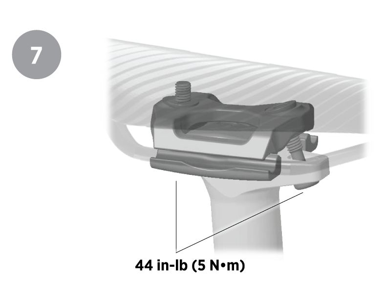
- Adjust the level and fore/aft position of the saddle. Then use a 4 mm hex wrench to tighten the saddle clamp bolts to 44 in-lb (5 N•m). (See Figure 7).
Using the Transfer Seatpost
Understand the basics before using your Transfer seatpost:
-
Press and hold the lever to change saddle heights. Release the lever when the post reaches the desired height.
-
Use your body to press the saddle down as you change to lower saddle height settings and to guide your saddle as it returns to higher settings.
-
When changing seatpost height, always release the remote lever first before releasing control of the saddle with your body.
-
Practice within your abilities to gain expertise in using the Transfer seatpost before using it in more technical riding situations.
Service Intervals
To best maintain the performance and durability of your product under normal use, FOX recommends that you have regular Transfer Seatpost maintenance performed according to the service intervals listed below.
| Recommended Minimum Transfer Maintenance | Every 25 Hours | Every 125 Hours | Every 300 Hours/Annually* |
| 2025 Transfer 25 Hour Simple Grease Service | X | ||
| 2025 Transfer 125 Hour Intermediate Service (Common shop tools only) | X | ||
| 2025 Transfer 300 Hour Full Rebuild (Common shop tools only) | X |
*For those who ride lift-accessed DH, Park, or Extreme Freeride or in extremely wet/muddy or dry/dusty environmental conditions where trail debris is sprayed onto the fork or shock while on the trail, FOX encourages riders to perform maintenance earlier than recommended above as needed. If you hear, see, or feel something unusual, stop riding immediately and contact a FOX Authorized Service Center for proper servicing.
Troubleshooting
| Symptom | Possible Cause | Check, in this order: | If yes, then adjust this: |
| Poor Return | Valve not Opening Fully | Is the cable tension too loose to fully open the valve? | Tighten lever barrel adjuster or cable clamp. Replace lever or barrel adjuster if damaged. |
| Is the cable housing kinked or dirty, keeping the cable from sliding smoothly to open the valve? | Replace cable and housing and/or adjust cable routing. When adjusting seatpost height be sure to push or pull cable housing from the lever side as necessary to keep the cable from kinking or stretching. | ||
| Is the seatpost is too deep in the frame causing the actuator to hit a frame member before the valve is fully open? | Move seatpost up in the frame. Travel adjust if necessary. | ||
| Low Gas Pressure | Does it feel like there is a weak return force near top out? | Increase air pressure up to 325 psi. Min functional pressure is 275 psi. Pressure can be adjusted to offset for pressure drop due to temperature changes. Note that if you re-install a shock pump on this seatpost to "check pressure" after re-charging, the air lost into the shock pump hose will cause presure to drop significantly (up to 100 psi), so checking pressure isn't effective. Instead, simply see if the seatpost is working properly to confirm you got the correct charge pressure. |
|
| High Friction | Has it been more than 25 hours of riding since re-grease? | Unthread collar and apply a heavy coat of slickhoney to upper post to re-lubricate bushings and seals. Detailed instructions: https://www.ridefox.com/fox17/help.php?m=bike&id=2992 | |
| Has it been more than 125 hours of riding since lower post service, or have you ridden in adverse conditions causing dirt and debris to enter the lower post? | Perform 125 hour service to clean and re-lubricate the bushings, wiper, etc.: https://www.ridefox.com/fox17/help.php?m=bike&id=2991 | ||
| Is the seatpost clamp over-torqued, causing 1 high friction spot in the travel? | Lower the torque to max 5 Nm, or the minimum required to hold the seatpost from sliding. Clean and apply friction paste to the lower post if necessary. Note seatpost clamp and frame designs vary greatly so necessary torque may vary. | ||
| Is the seatpost clamp slot aligned with the slot in the frame? | Rotate the seatpost clamp so it is aligned opposite of any slots in the frame. This avoids a "pinch spot" where the lower post deforms and binds on the lower bushing. | ||
| Is the saddle clamp hardware over-torqued? | Torque saddle clamp hardware to 5 Nm. | ||
| "Dead spot" near top out | Is there a region of zero gas force near top out where the post freely moves up and down when the lever is actuated? | Oil level is too low, causing IFP to bottom out. Hydraulic re-bleed is needed. Perform full rebuild: https://www.ridefox.com/fox17/help.php?m=bike&id=2924 | |
| Off-bike check | Check the post off the bike, with no cable attached, by pressing the lever on the bottom of the post with your thumb. Does it still return slowly? | If not, re-check the items above. | |
| Creeps down under rider weight | Valve not closing fully | Is the cable too tight at the lever? | Turn lever barrel adjuster in until it just takes the slack out of the cable, do not over-tighten. |
| Is the cable anchor (end of cable at bottom of the seatpost) fully seated in the cable bushing? | Make sure the cable anchor is fully seated, if not it can keep the valve from closing. | ||
| Is something preventing your lever from returning freely or completely? | Check lever function, visually ensure no damage, fix/replace as needed. | ||
| Is the cable housing kinked, dirty, or stretched, keeping the cable from sliding smoothly to close the valve? | Replace cable and housing and/or adjust cable routing. When adjusting seatpost height be sure to push or pull cable housing from the lever side as necessary to keep the cable from kinking or stretching. | ||
| Is the seatpost is too deep in the frame, causing the actuator to hit a frame member and open the valve? | Move seatpost up in the frame. Travel adjust if necessary. | ||
| For all symptoms: | If you've checked the items above, and the post isn't working properly, please contact your local FOX Service Center to arrange for diagnosis and service. | ||
| - In the USA and Canada, you can request a Return Authorization number directly at this link: https://www.ridefox.com/rarequest.php?m=bike. | |||
| - For riders in other countries, you can find your regional service center here: https://www.ridefox.com/contact.php?c=worldwide&type=bike&country= |
