32mm/34mm/36mm/38mm/40mm Dust Wiper Replacement
Required Parts
- 025-03-010 Oil: AM, FOX Bath Oil [32 oz.], 20 WT Gold
- 025-03-023 Oil: Suspension Fluid, 5wt, Teflon Infused, 1.0 US Quart
- 025-03-063 Oil: Suspension Fluid, 4 WT, 1.0 Liter Bottle
- 803-00-933 Kit: Dust Wiper, Forx, 36mm, Low Friction, No Flange
- 803-00-944 Kit: Dust Wiper, Forx, 32mm, Low Friction, No Flange
- 803-00-945 Kit: Dust Wiper, Forx, 34mm, Low Friction, No Flange
- 803-00-946 Kit: Dust Wiper, Forx, 40mm, Low Friction, No Flange
- 803-01-493 Kit: Dust Wiper, Forx, 38mm, Low Friction, No Flange
Required Tools
- 398-00-681 32 Damper-side and ALL 32-34-36-38-40 Spring-side Removal Tool
- 398-00-682 34-36-38-40 Damper-side Removal Tool
- 398-00-770 Tooling: Guided Fork Seal Driver, One Piece Seal/Wiper, 32
- 398-00-771 Tooling: Guided Fork Seal Driver, One Piece Seal/Wiper, 34
- 398-00-772 Tooling: Guided Fork Seal Driver, One Piece Seal/Wiper, 36
- 398-00-773 Tooling: Guided Fork Seal Driver, One Piece Seal/Wiper, 40
- 398-00-774 Tooling: Guided Fork Seal Driver, One Piece Seal/Wiper, 38
The following procedure guides you through dust wiper replacement for 2016+ 32mm, 34mm, 36mm, 38mm, 40mm forks.
WARNING: Always wear safety glasses and protective gloves during service to prevent potential injury. Failure to wear protective equipment during service may lead to SERIOUS INJURY OR DEATH.
These instructions can be utilized for basic guidance on dust wiper replacement for older pre-2016 model forks. Please consult the appropriate oil volume chart if servicing a pre-2016 fork and note that some details may have changed . Pre-2016 bath oil volumes can be found under "Fork- Basic Maintenance" by clicking: All Service Procedures »
WARNING: FOX products should be serviced by a trained bicycle service technician, in accordance with FOX specifications. If you have any doubt whether or not you can properly service your FOX product, then DO NOT attempt it. Improperly serviced products can fail, causing the rider to lose control resulting in SERIOUS INJURY OR DEATH.
WARNING: FOX suspension products contain pressurized nitrogen, air, oil, or all 3. Suspension misuse can cause property damage, SERIOUS INJURY OR DEATH. DO NOT puncture, incinerate or crush any portion of a FOX suspension product. DO NOT attempt to disassemble any portion of a FOX suspension product, unless expressly instructed to do so by the applicable FOX technical documentation, and then ONLY while strictly adhering to all FOX instructions and warnings in that instance.
WARNING: Modification, improper service, or use of aftermarket replacement parts with FOX forks and shocks may cause the product to malfunction, resulting in SERIOUS INJURY OR DEATH. DO NOT modify any part of a fork or shock, including the fork brace (lower leg cross brace), crown, steerer, upper and lower leg tubes, or internal parts, except as instructed herein. Any unauthorized modification may void the warranty, and may cause failure or the fork or shock, resulting in SERIOUS INJURY OR DEATH.
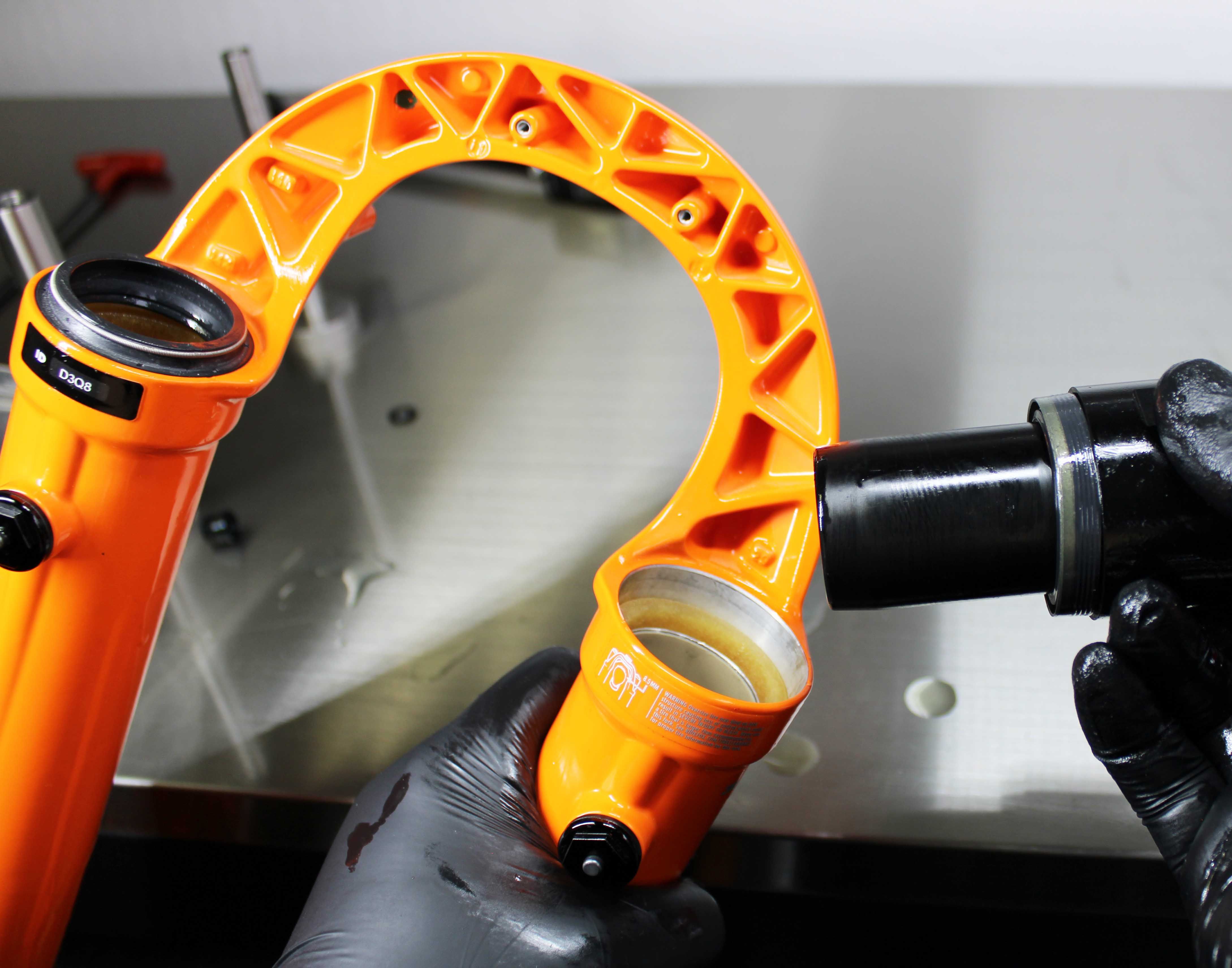
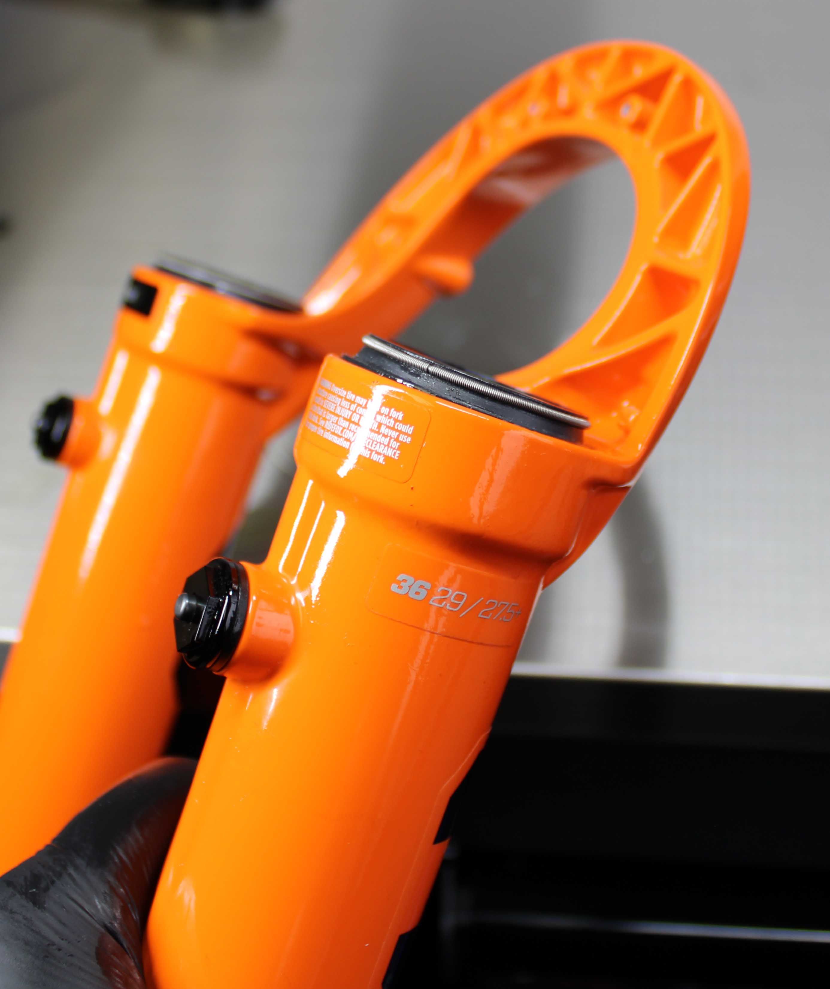
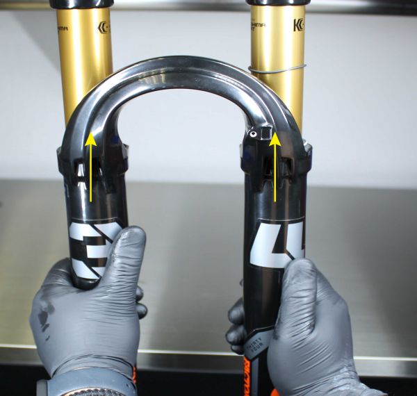
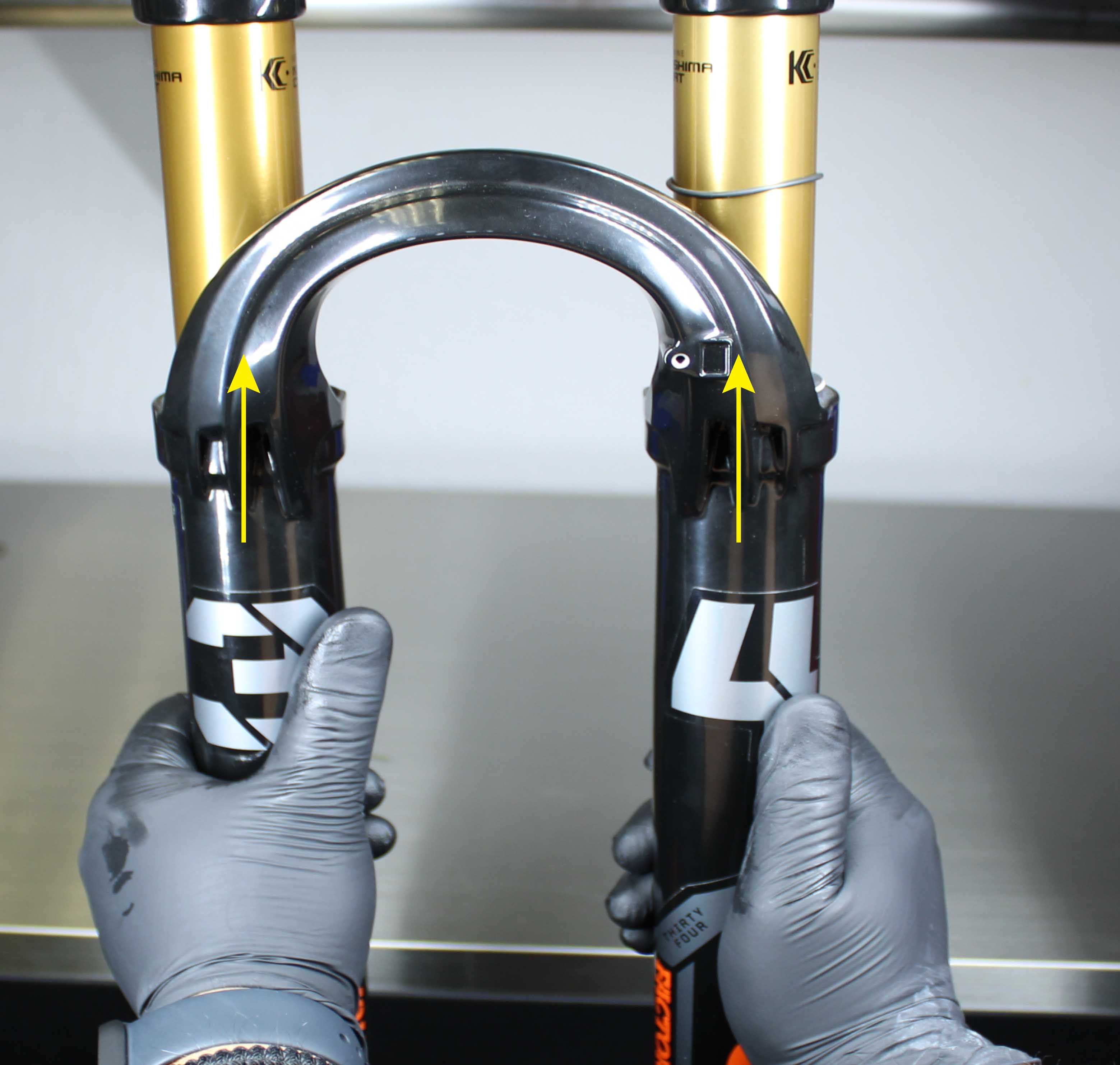
Various fork models shown, these same instructions will apply for 32mm- 40mm fork models.( 32TC requires special tooling to remove Bottom Nuts, see 32TC Service procedure for instructions )
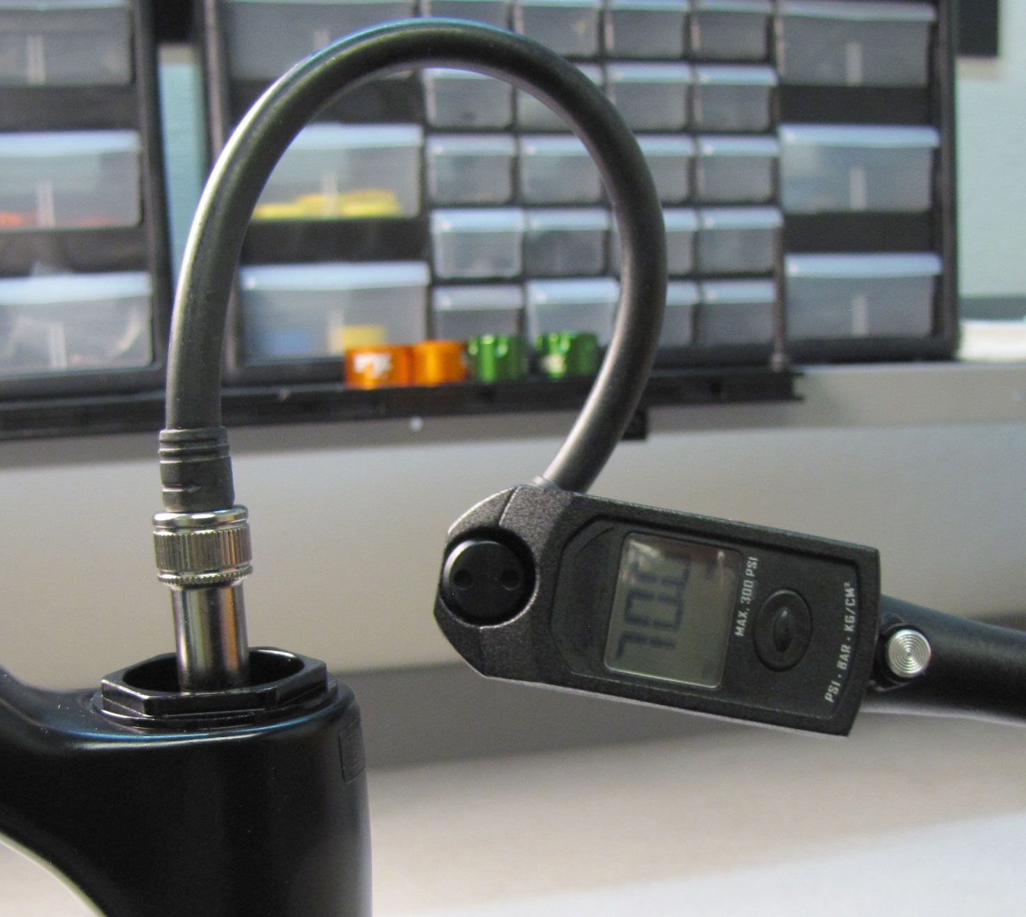
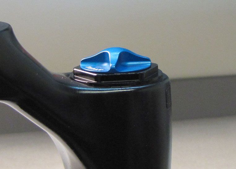
Step 1
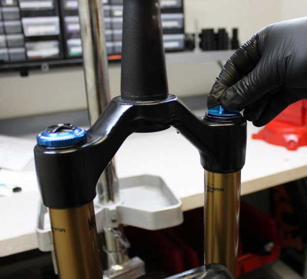
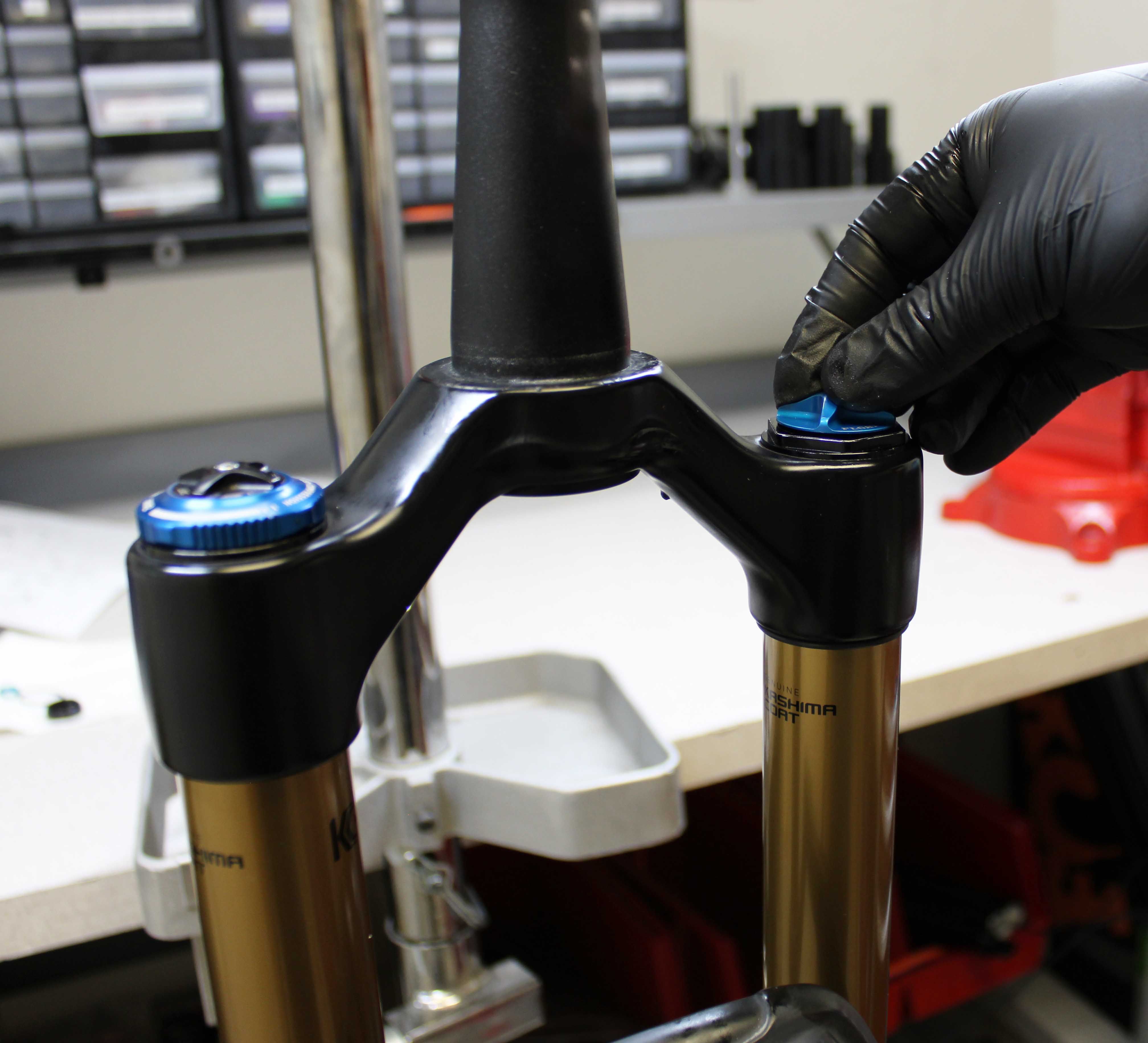
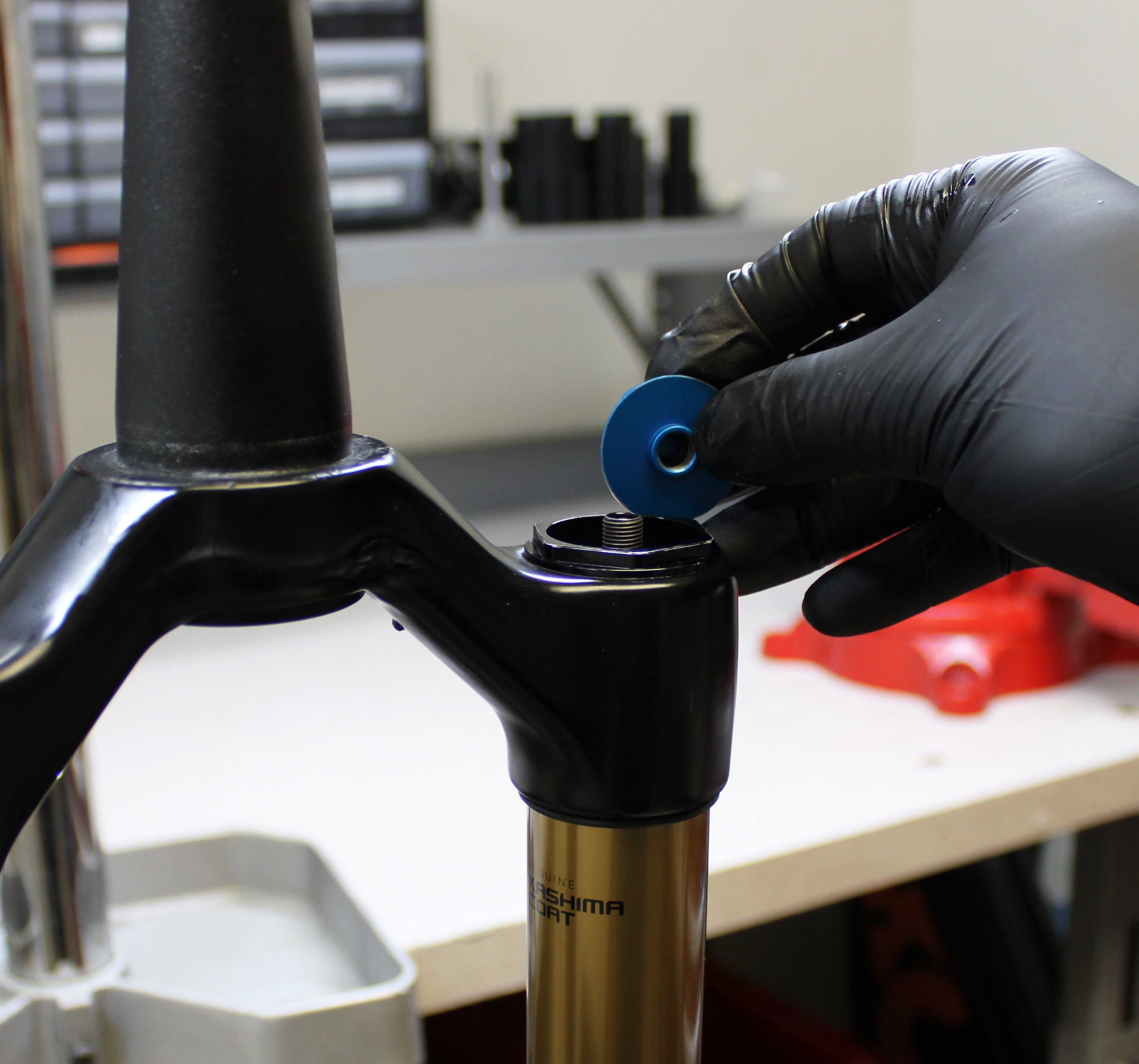
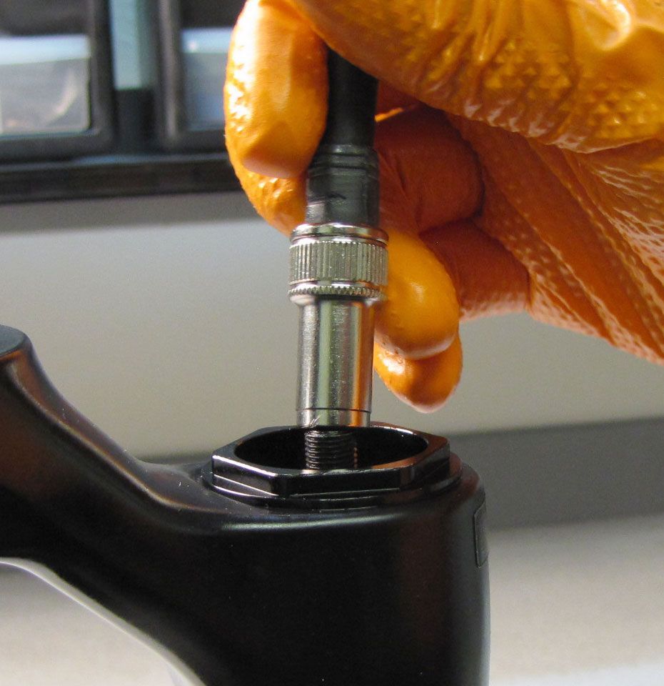
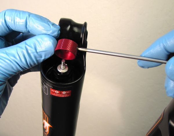
Remove the blue air cap and cover the air valve with a rag as you release the air pressure.
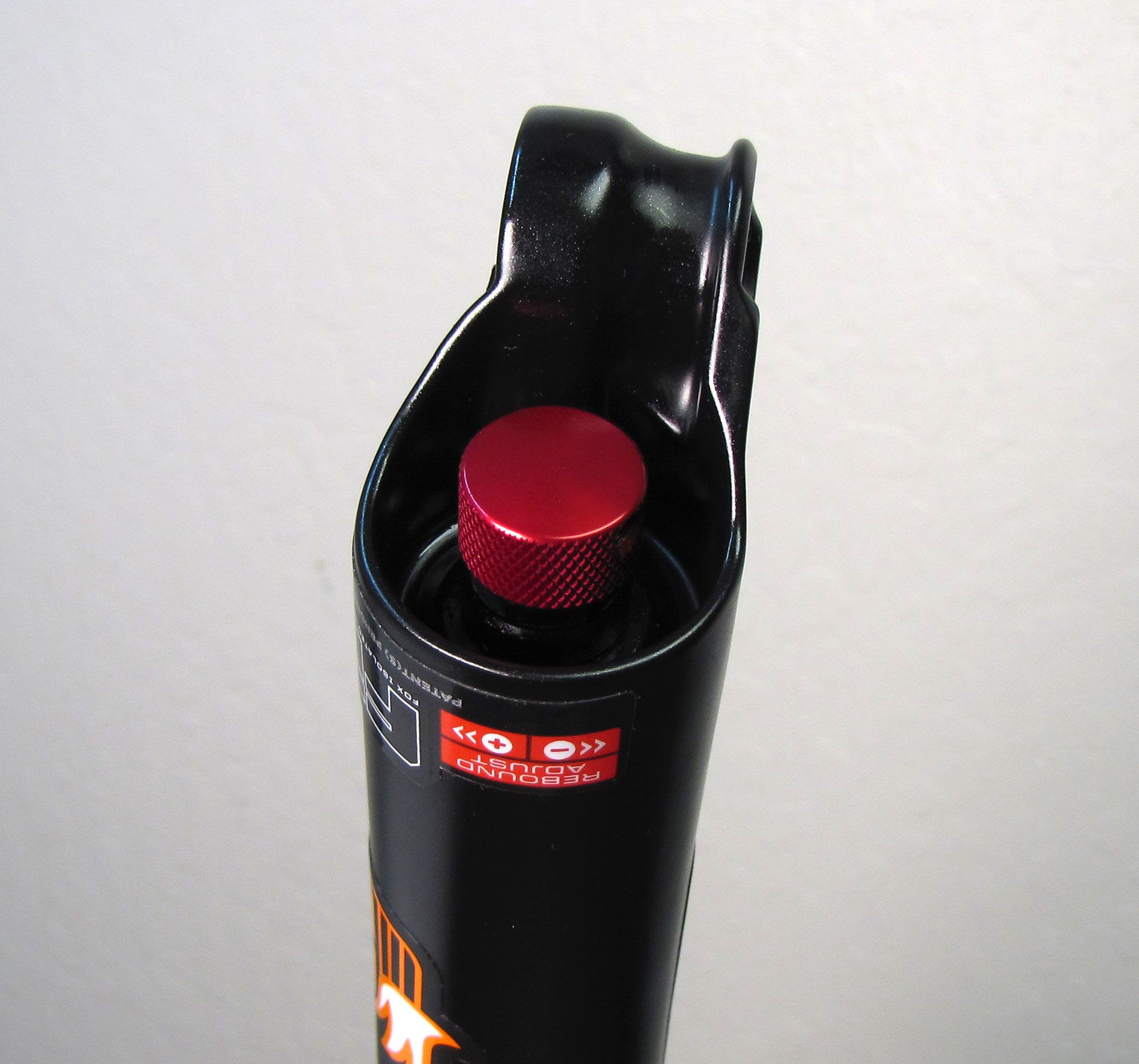
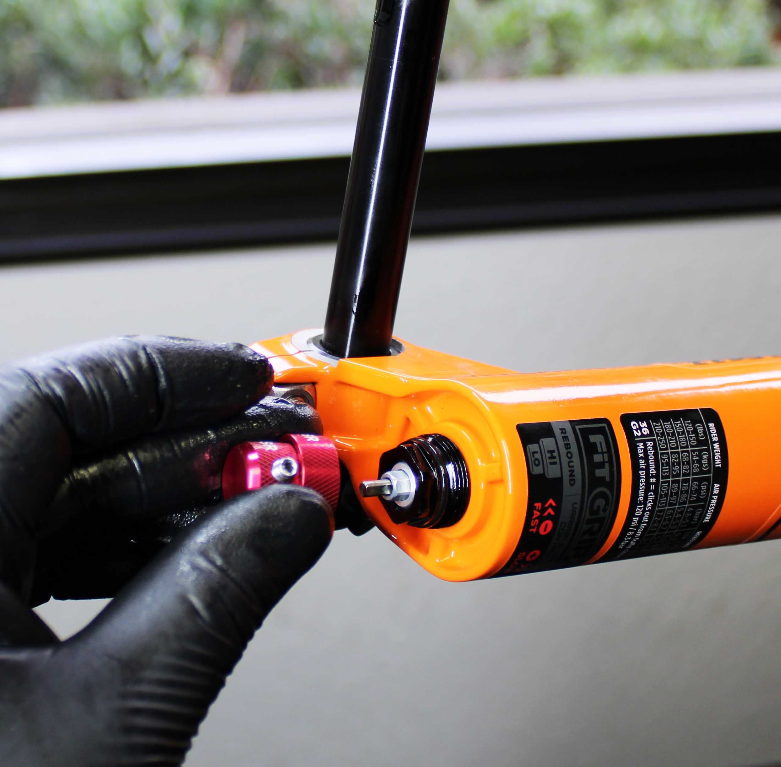
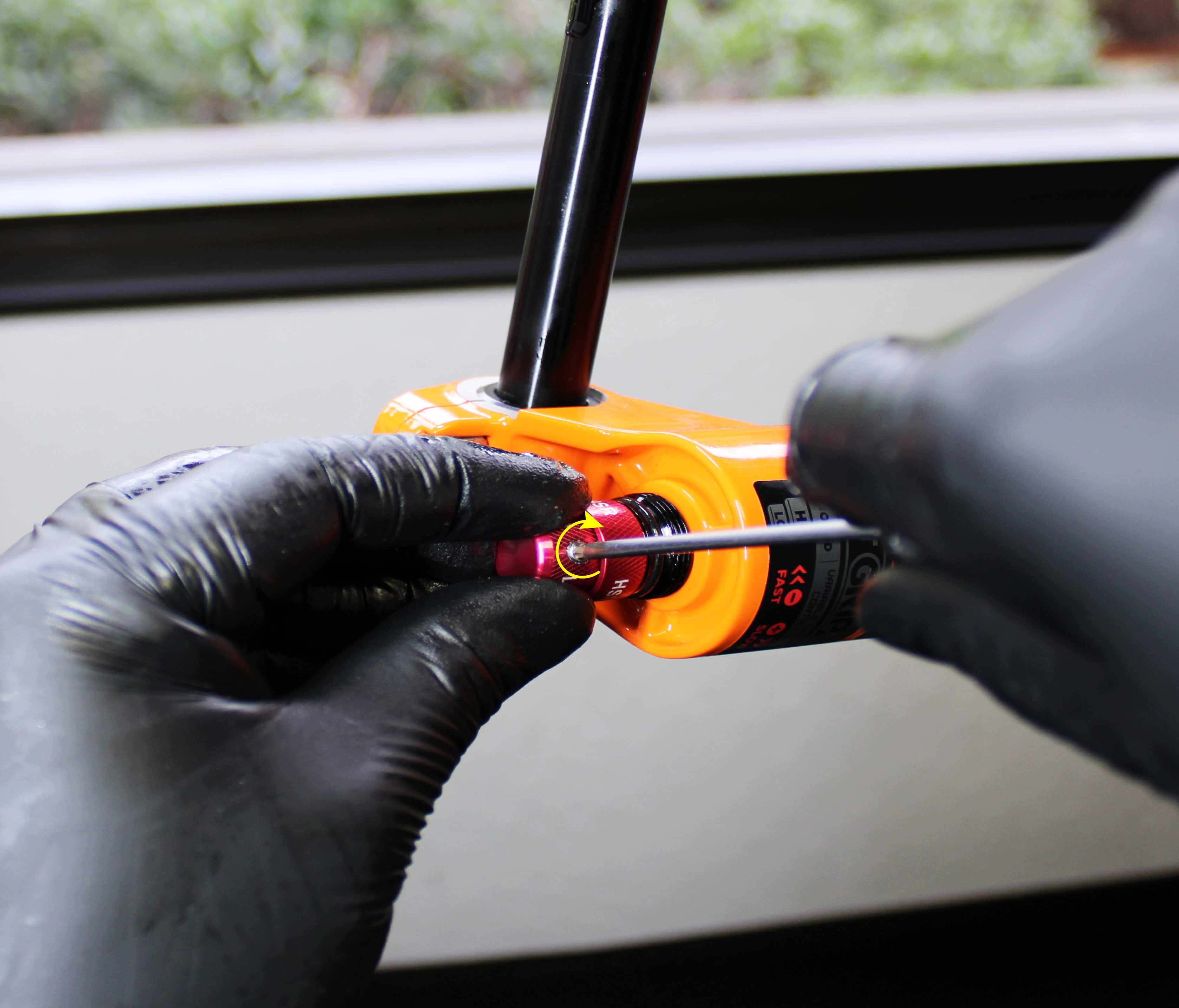
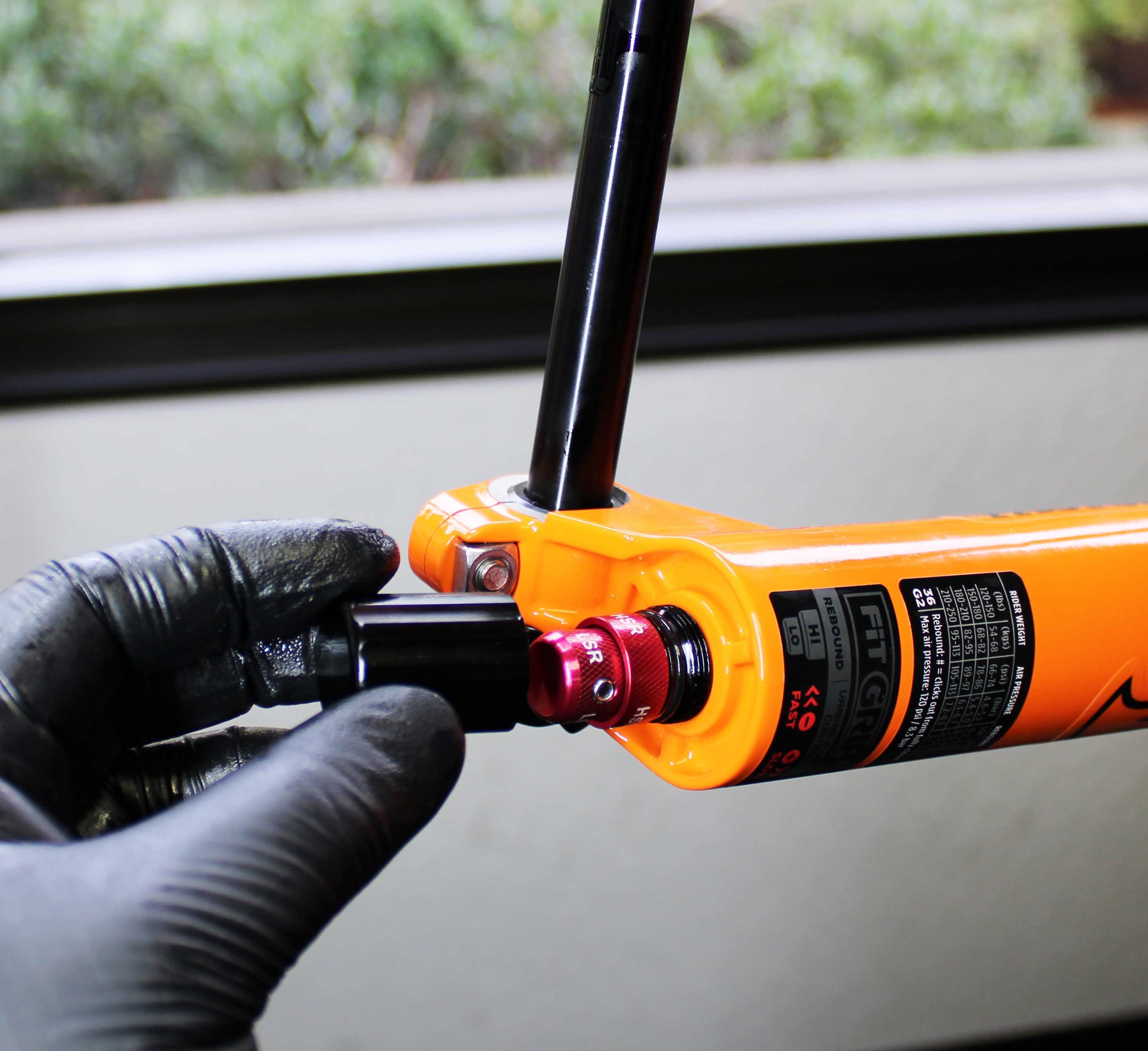
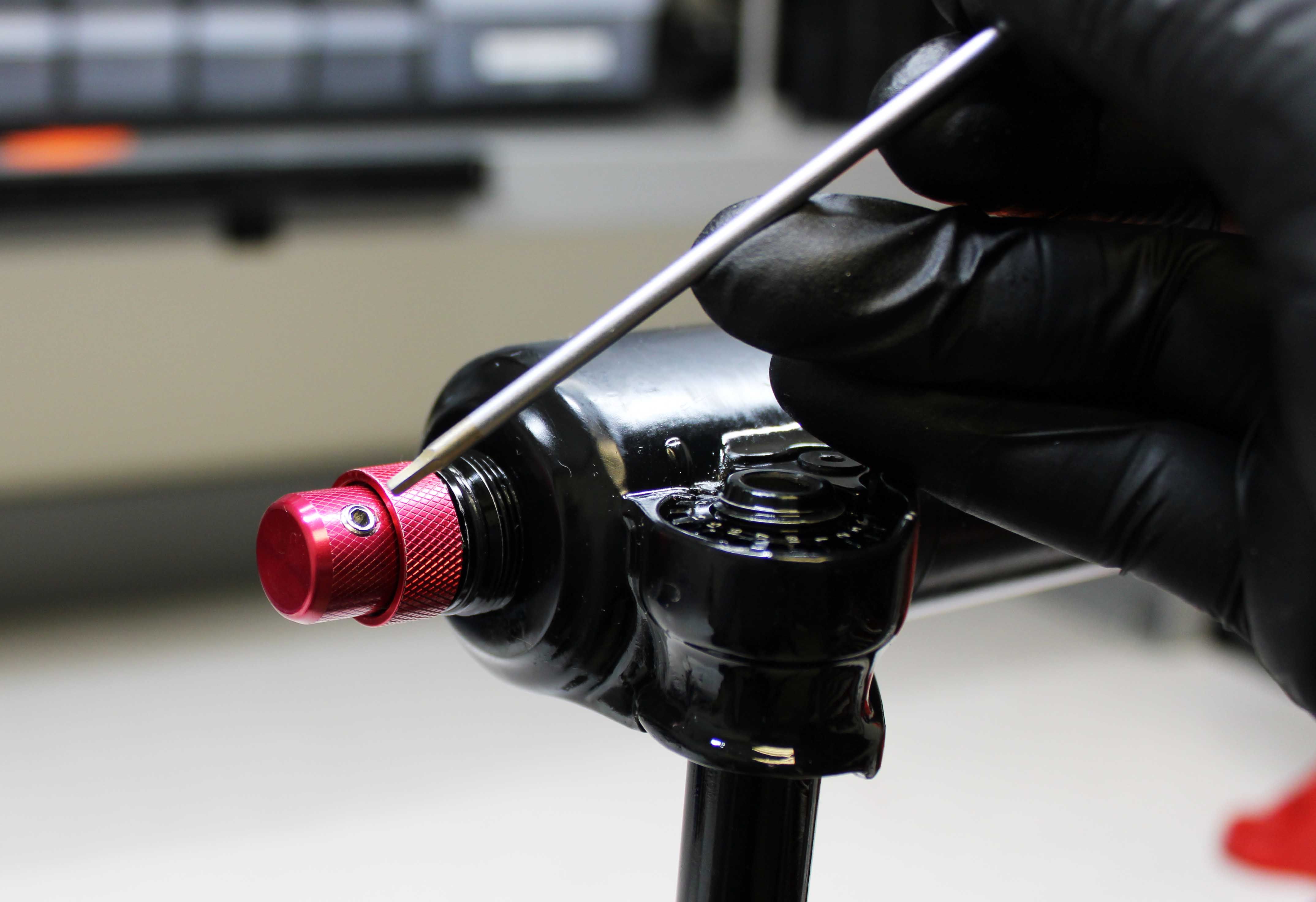
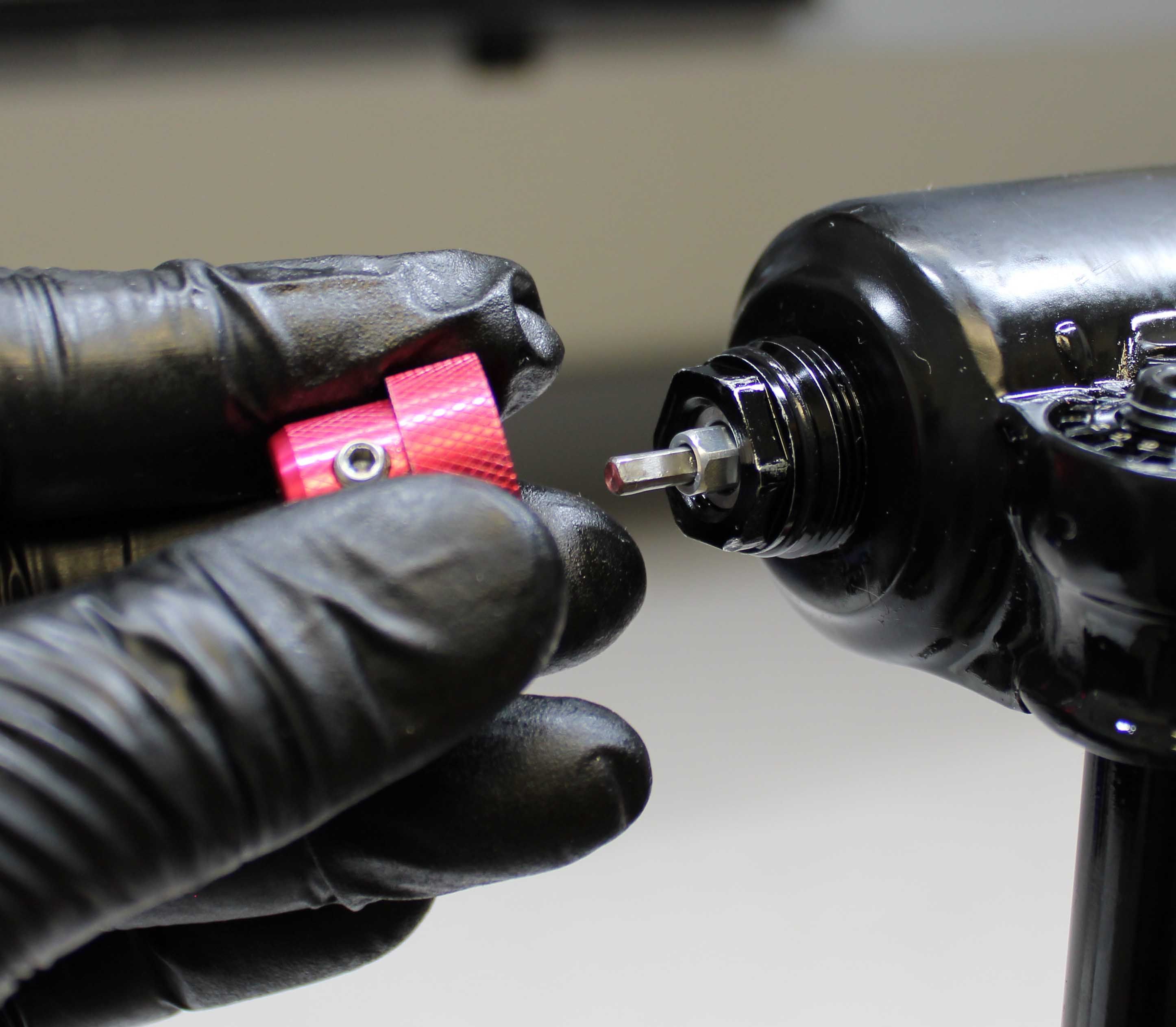
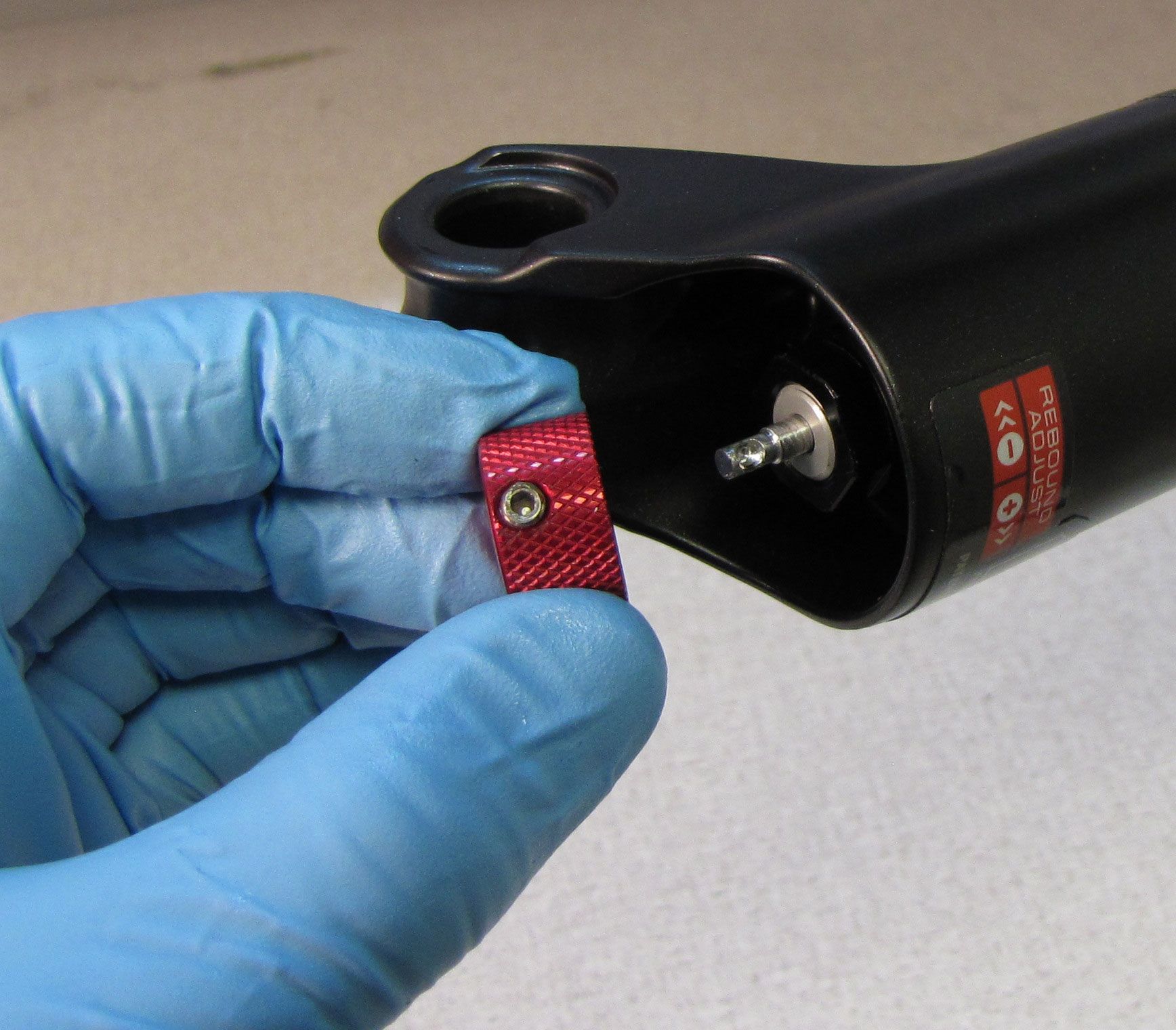
Step 2
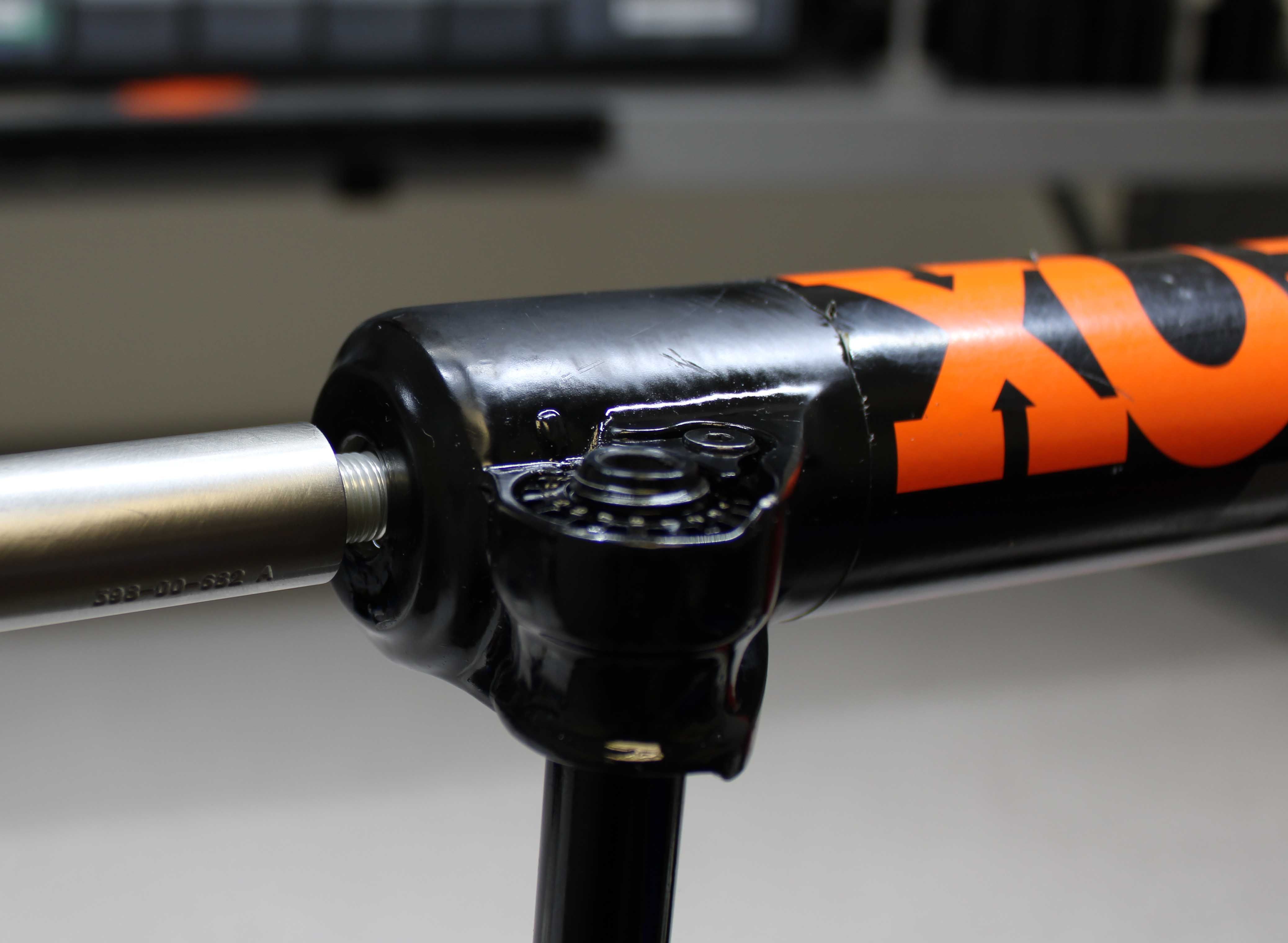
Remove the rebound knob cover (where present). Use a 2mm hex wrench to unthread the set screw in the red rebound knob, remove the knob and set it aside.


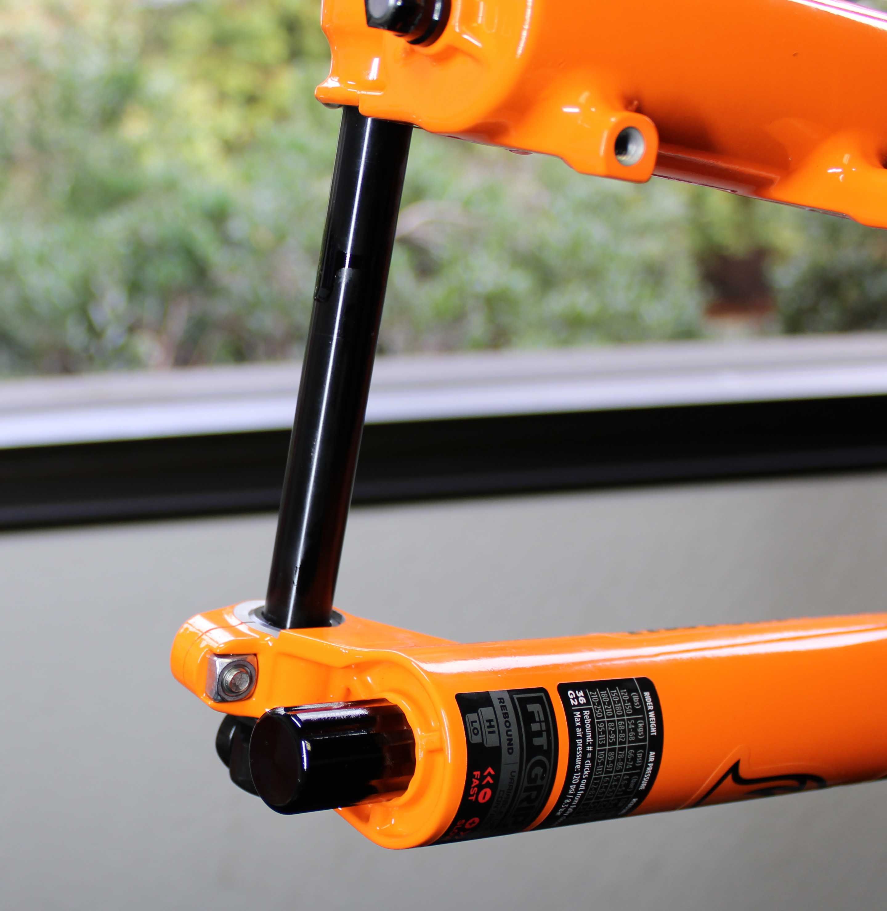
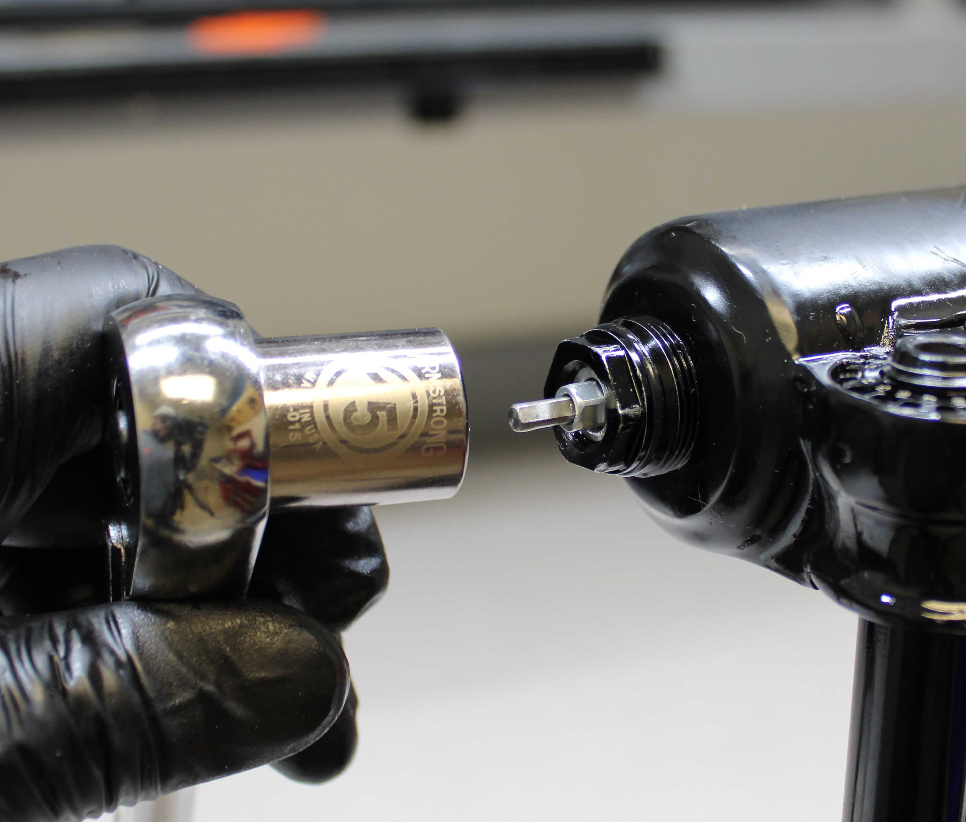
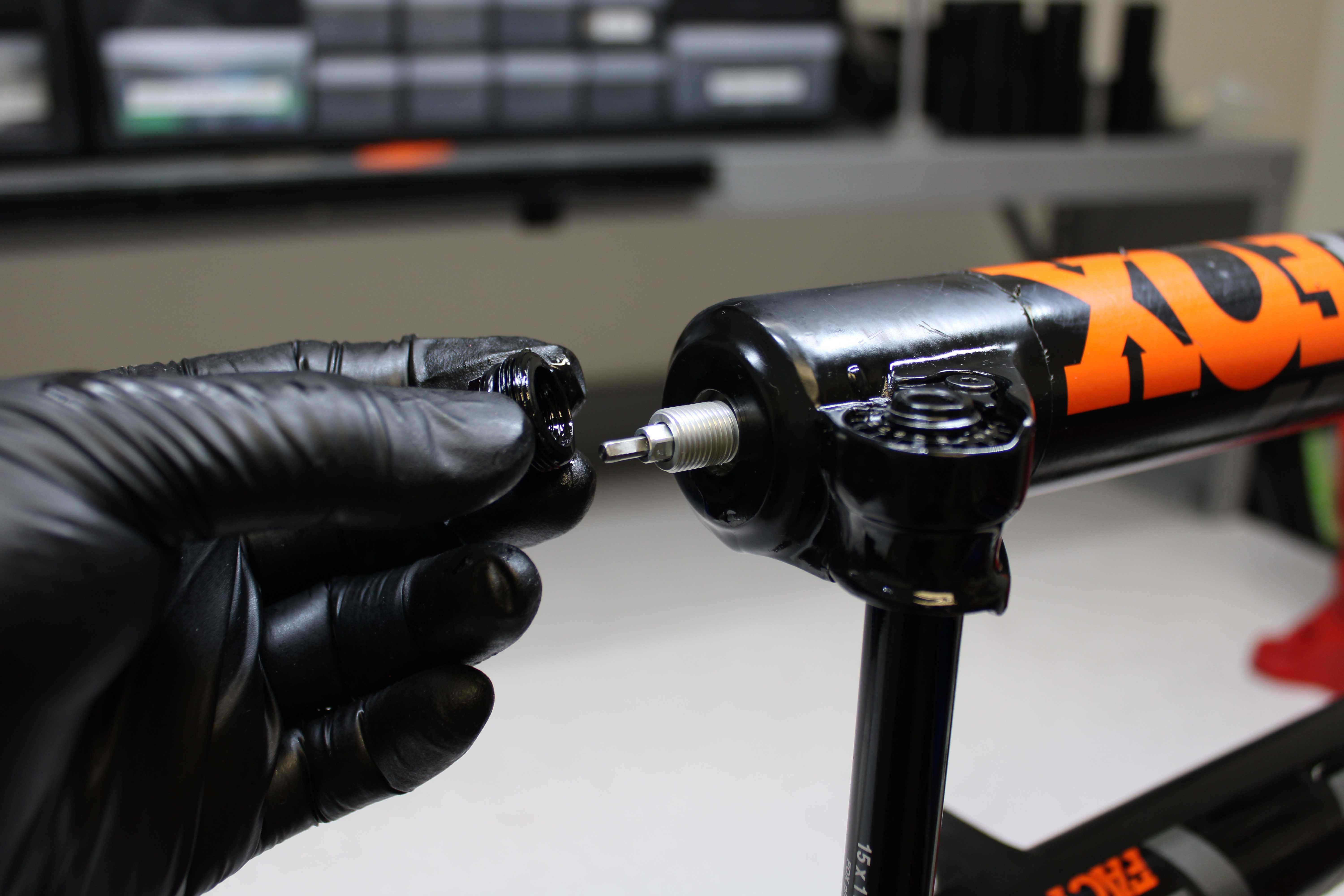
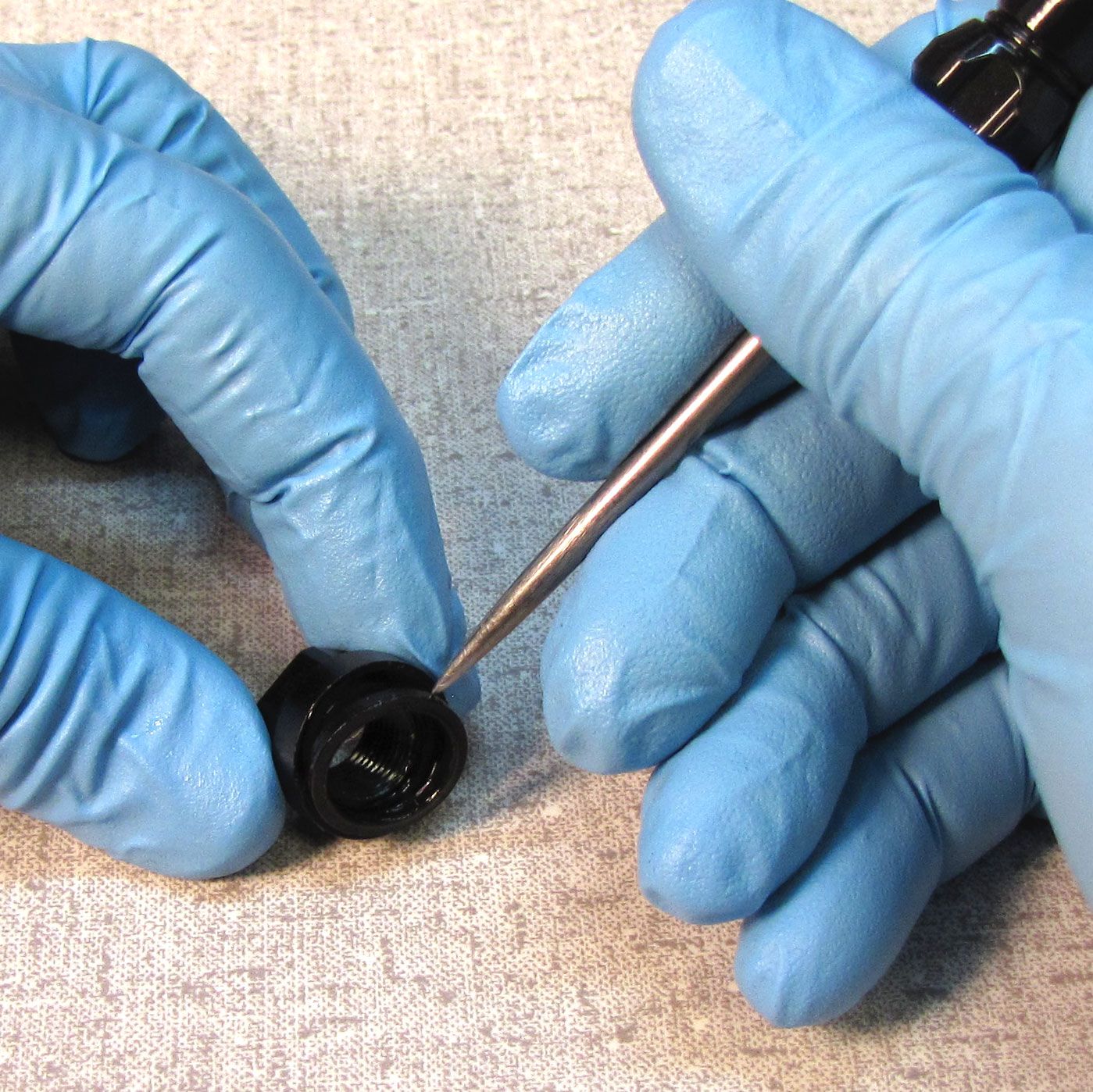
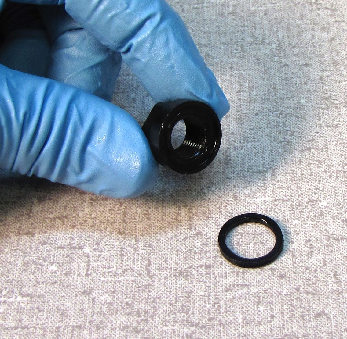
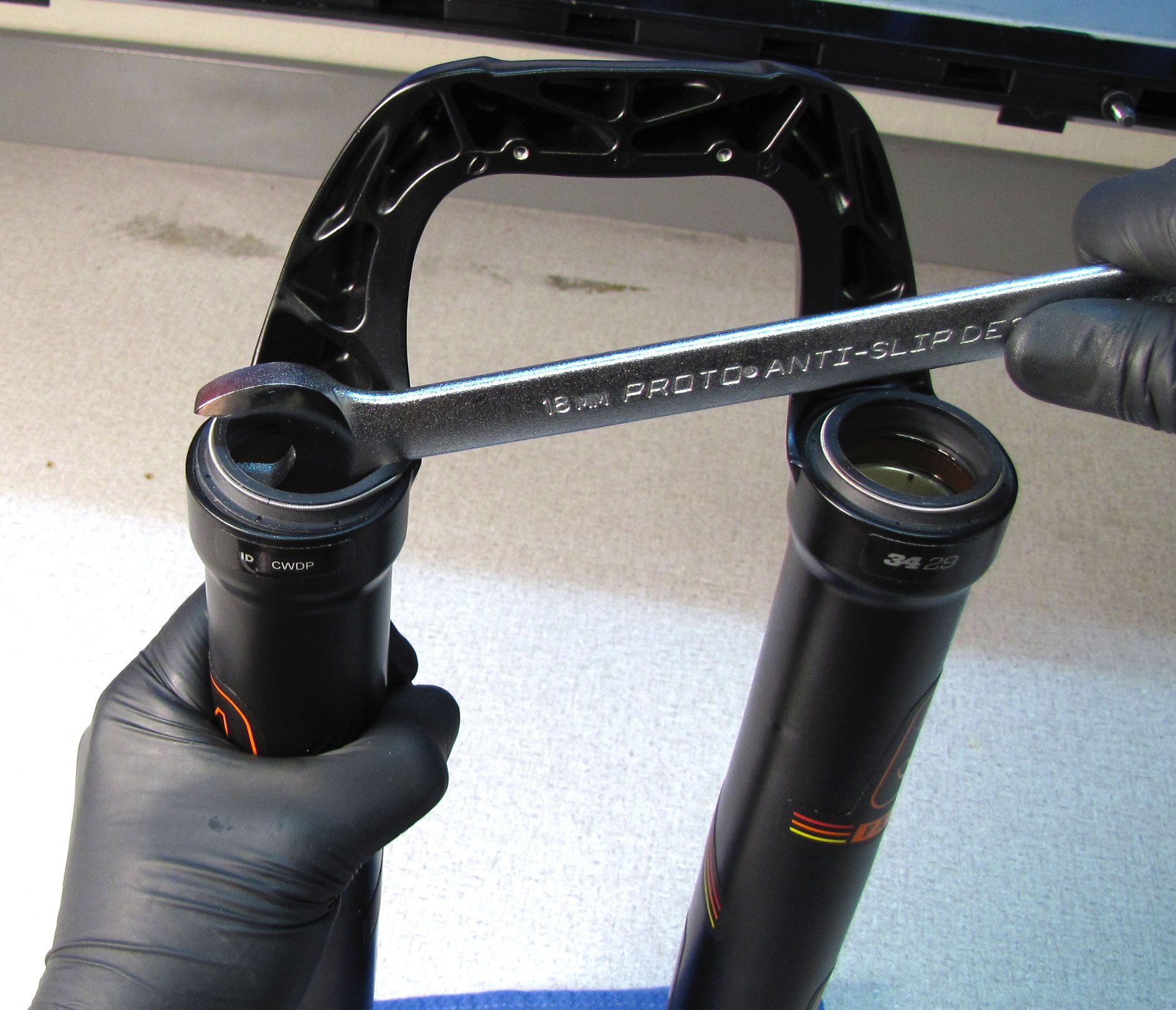
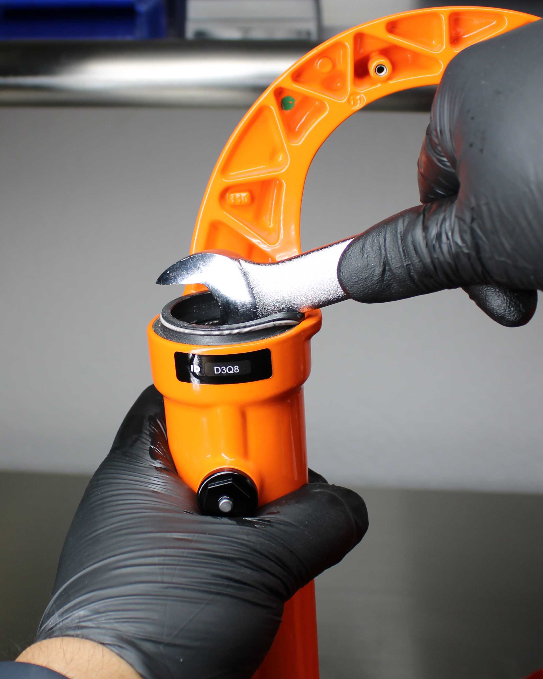
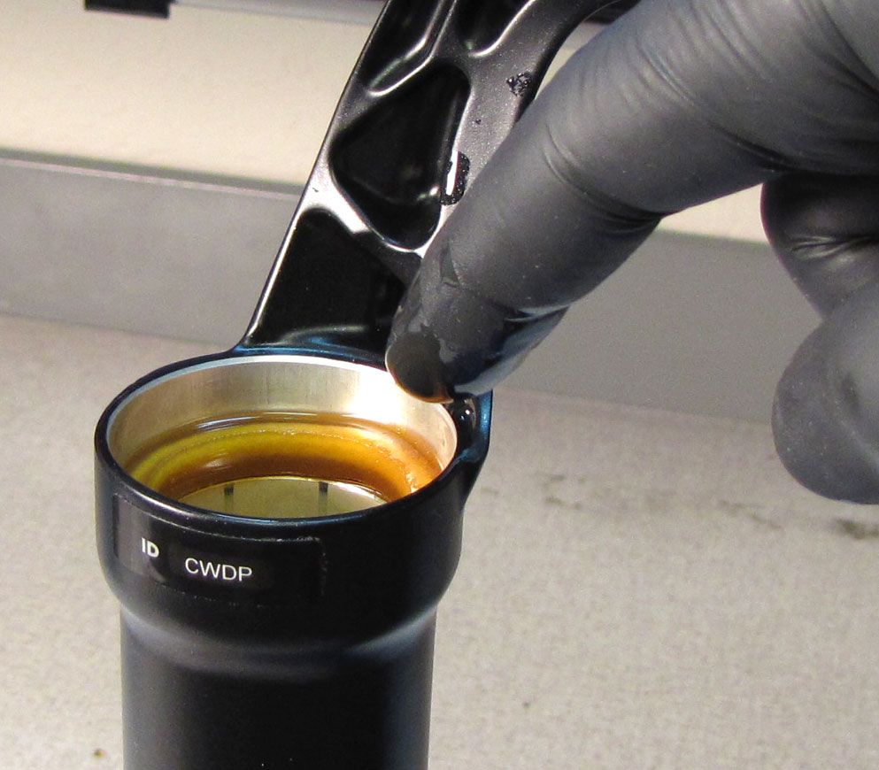
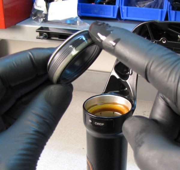
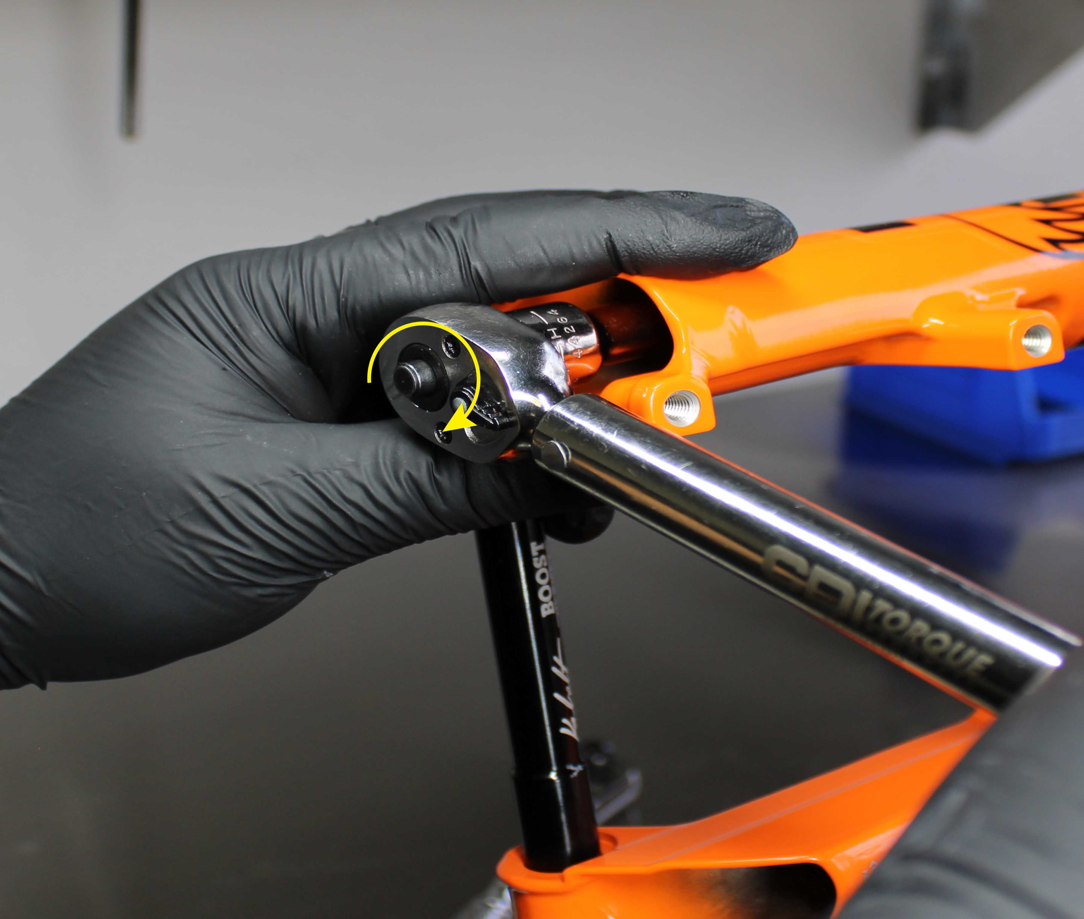
Step 3
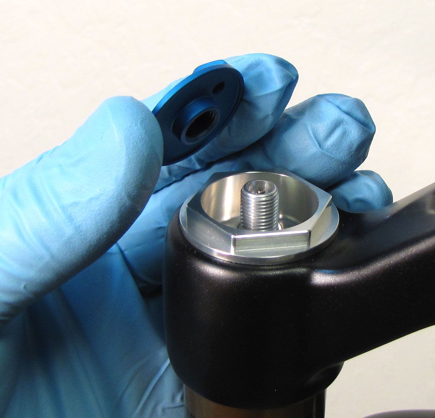
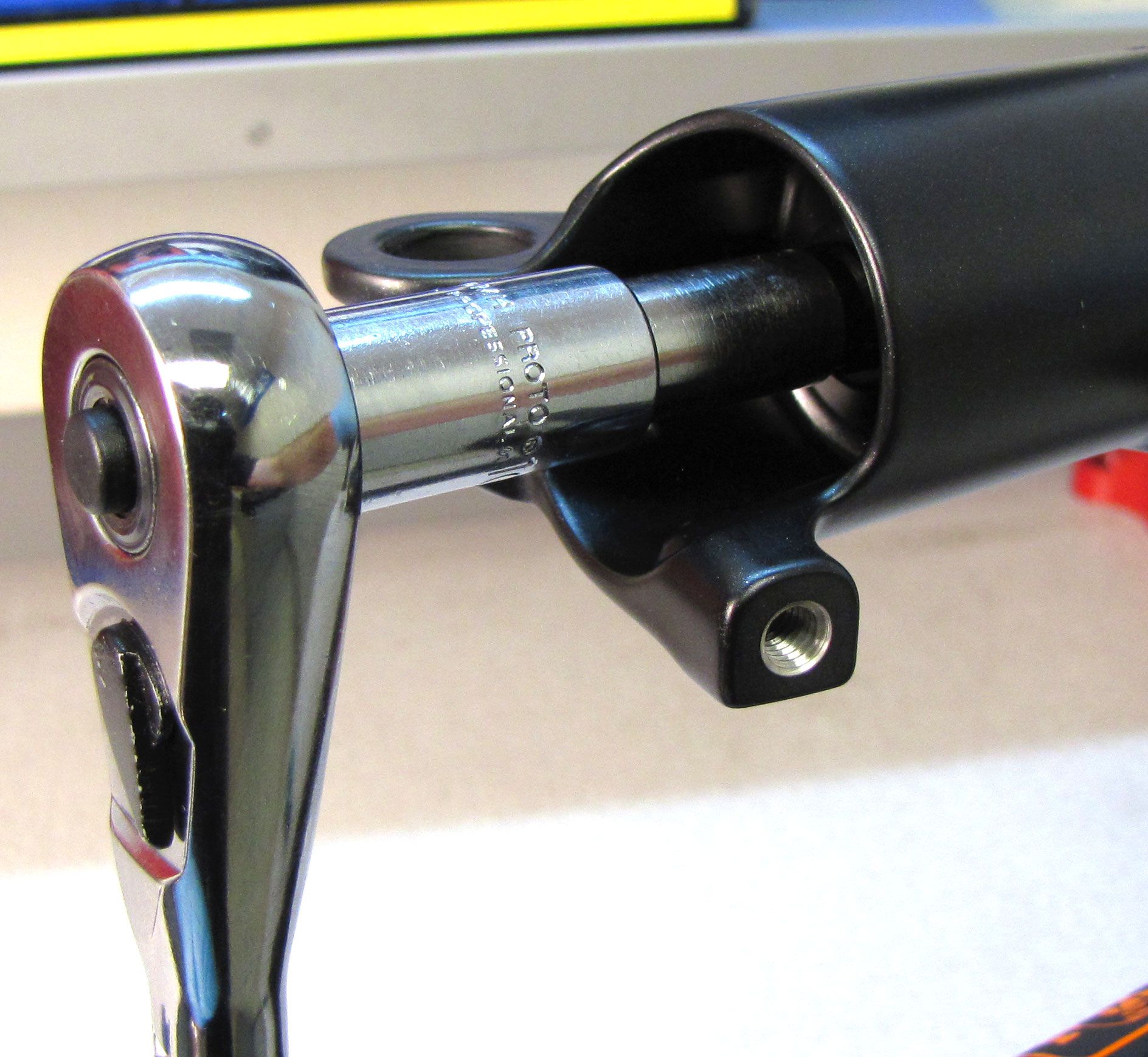
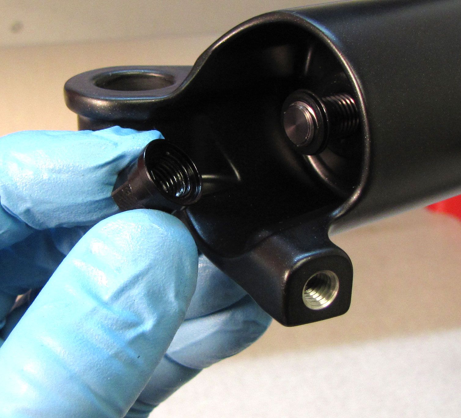
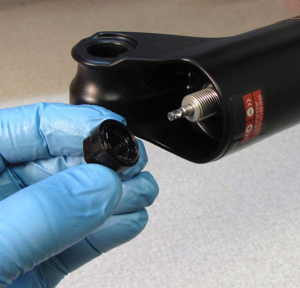
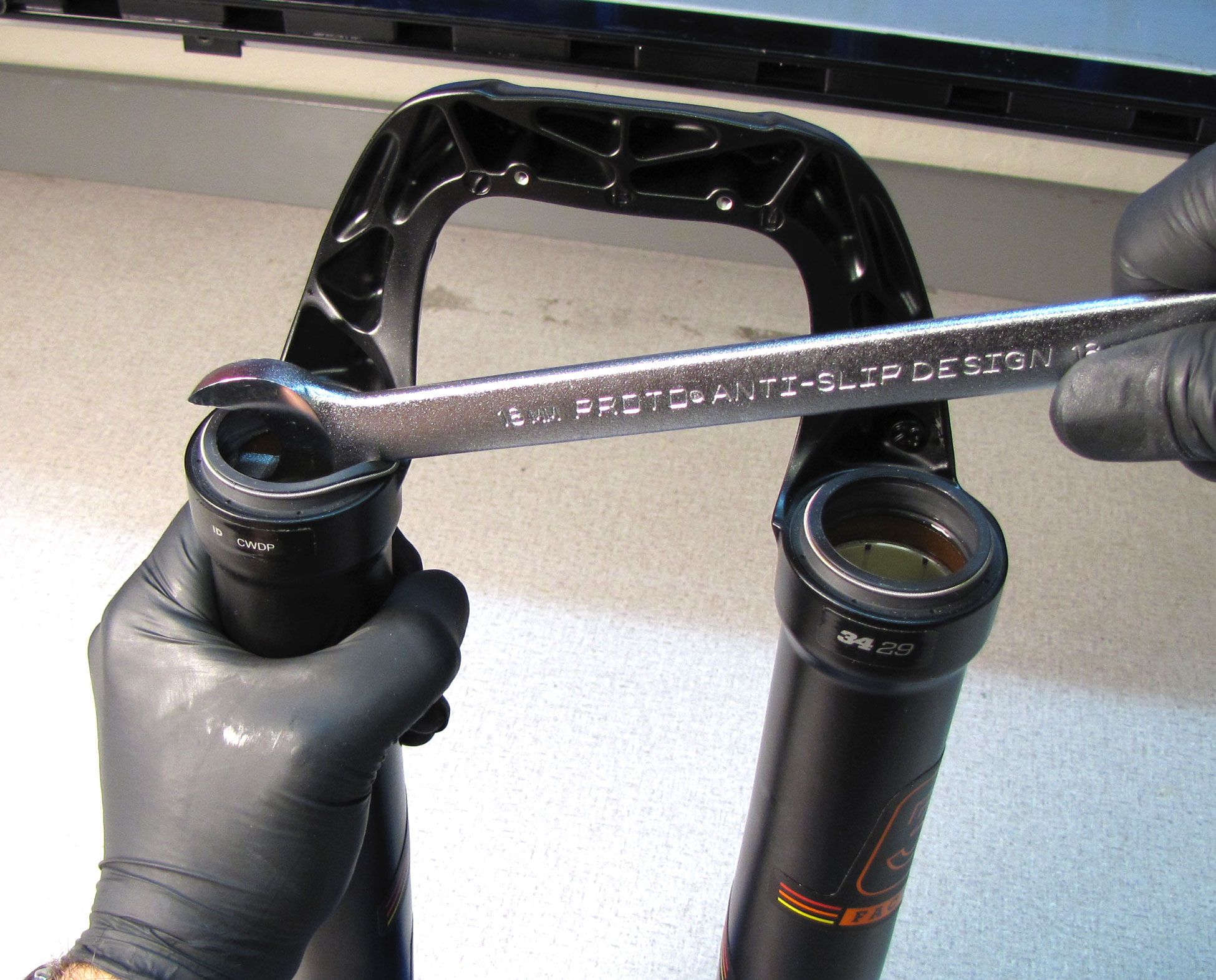
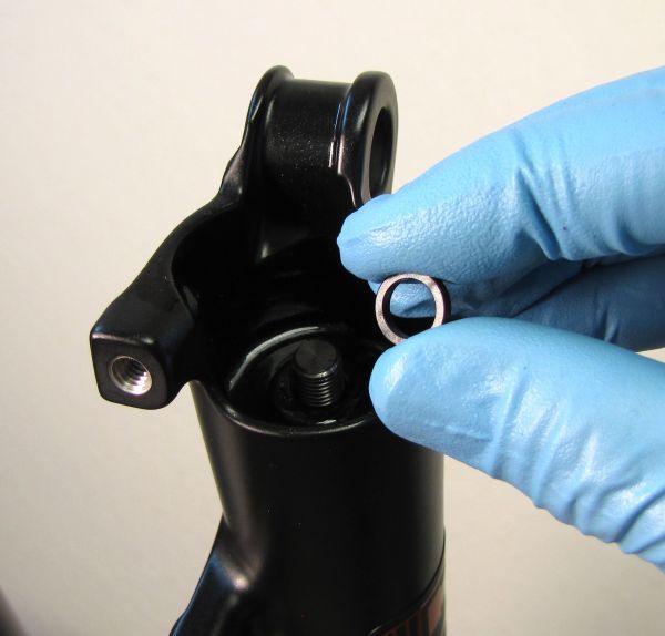
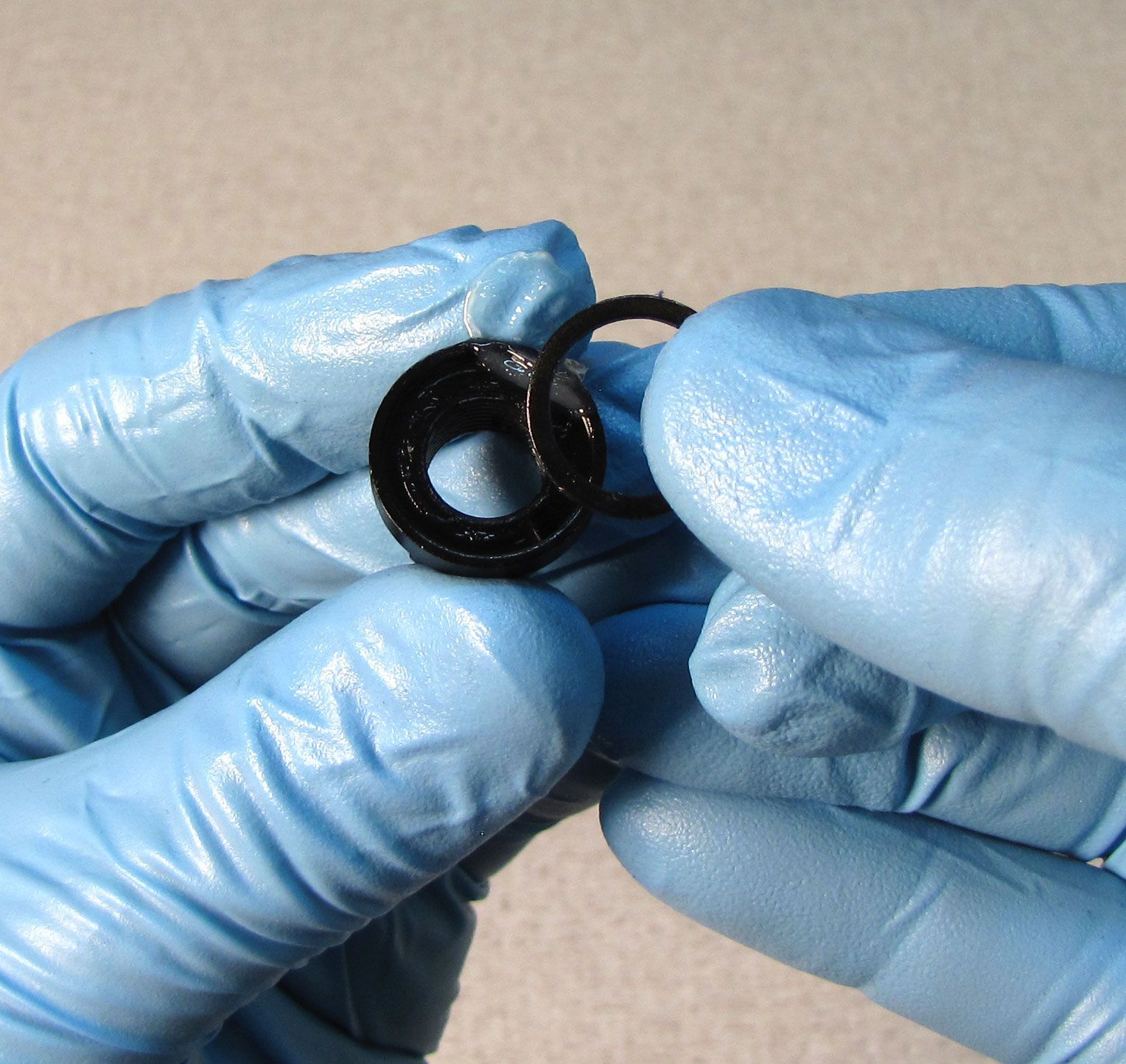
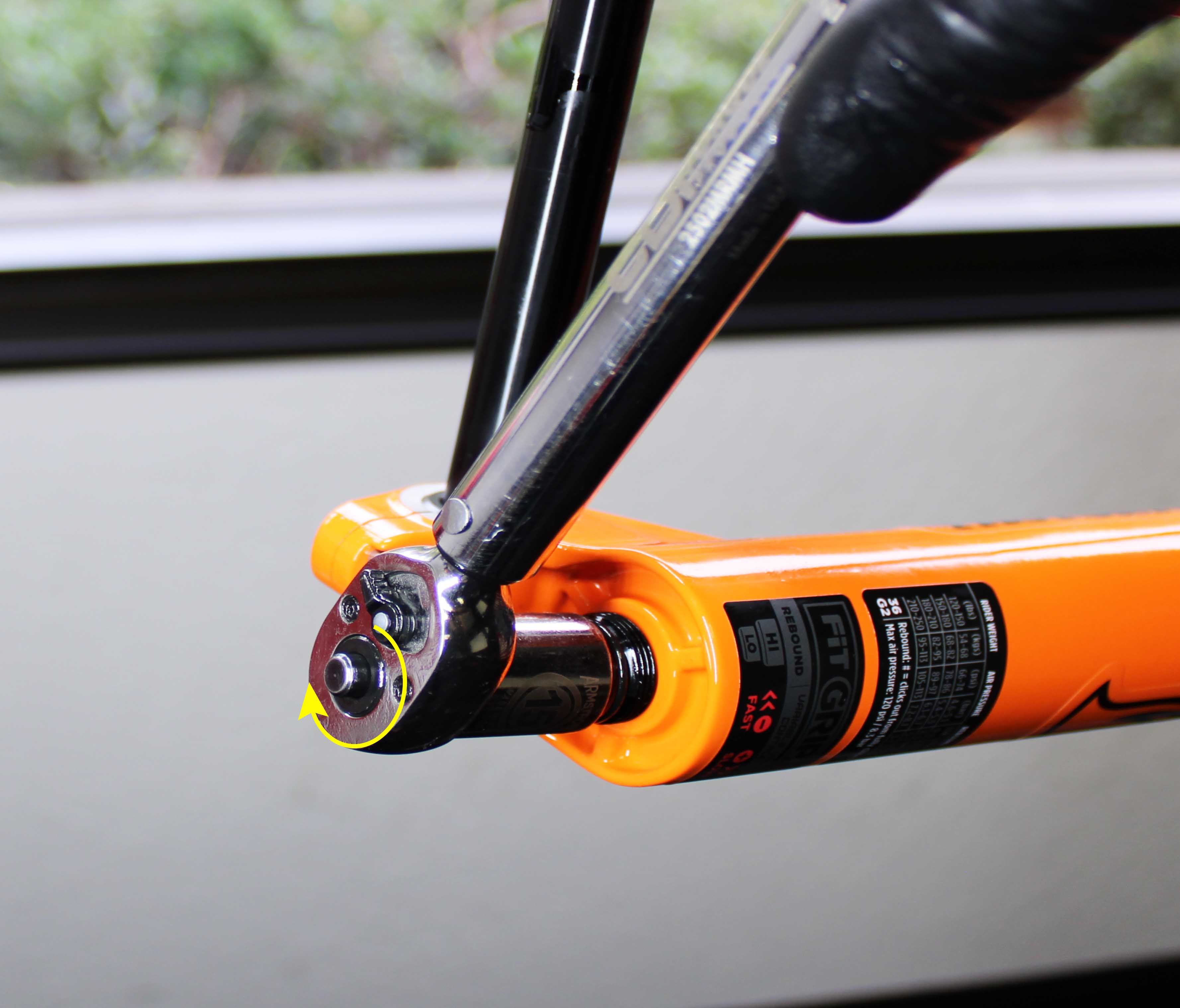
Use a 10mm socket (a thin-walled socket may be needed for certain forks including Step-Cast models) to unthread (counter-clockwise) and remove the air side bottom nut. Remove and discard the original crushwasher.
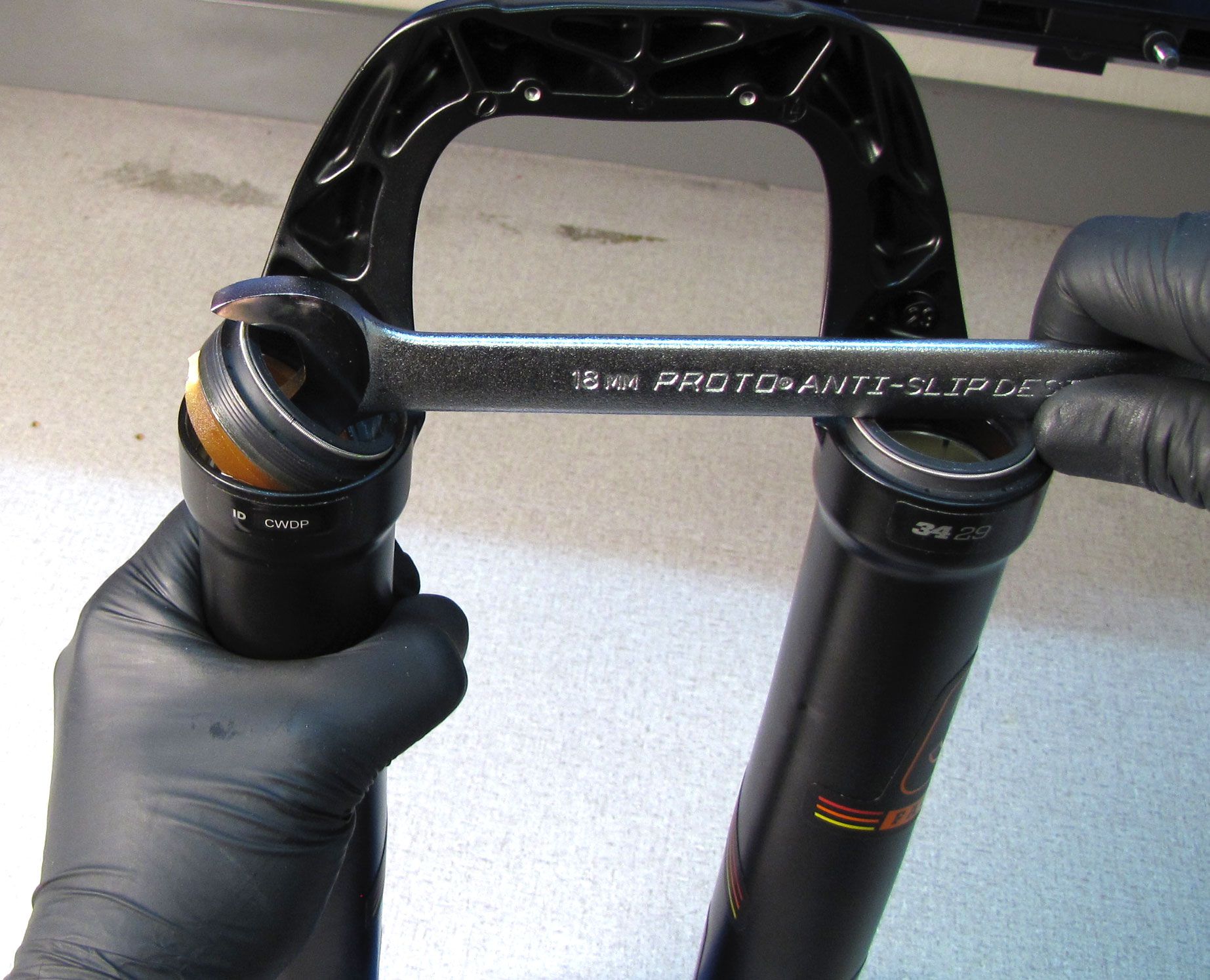
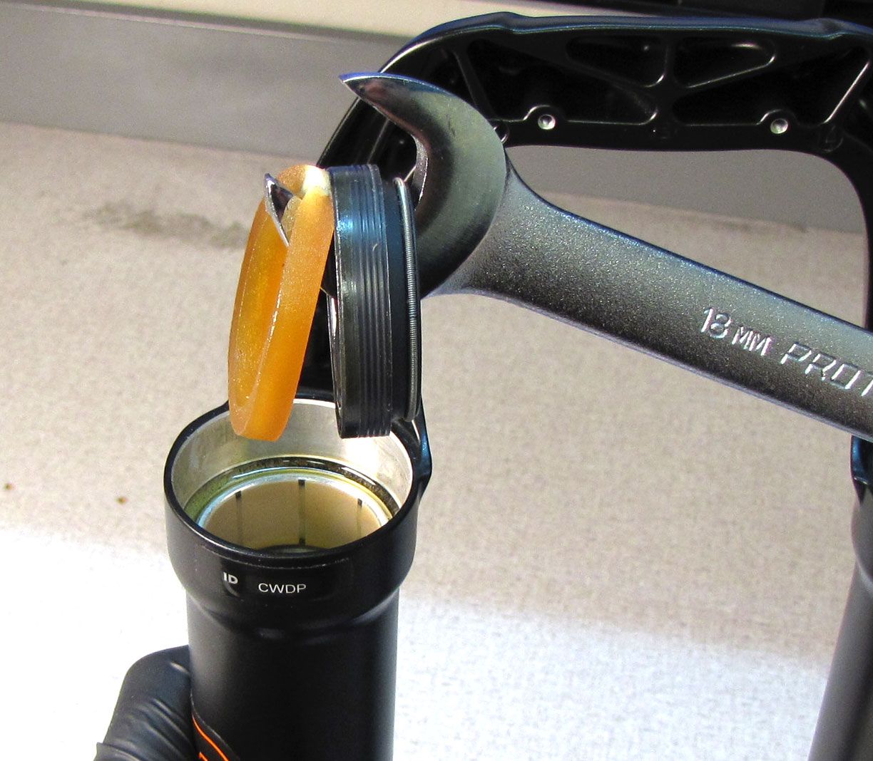
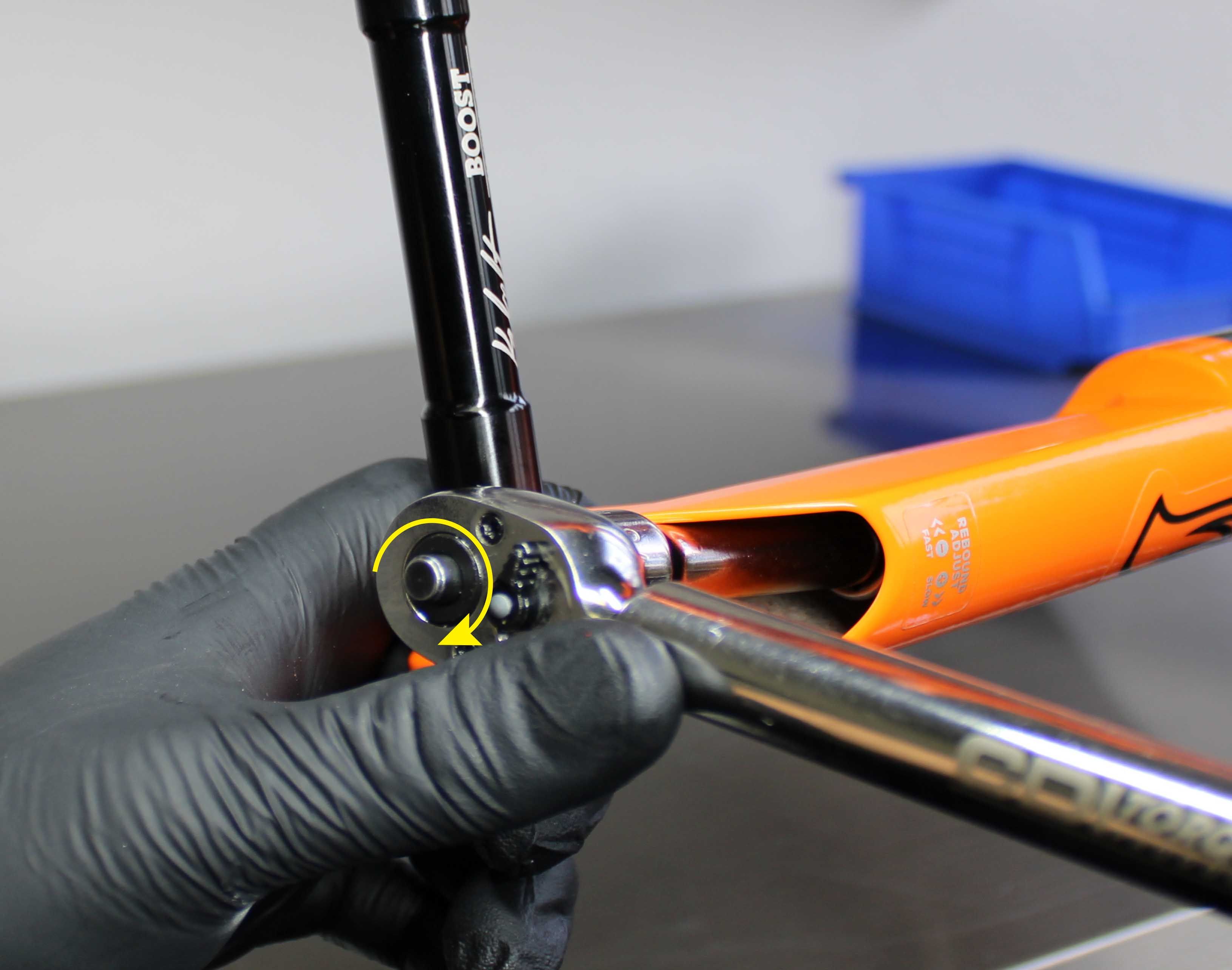
Step 4
32mm: Use a 10mm socket to remove the damper side bottom nut. Remove and discard the original crushwasher.
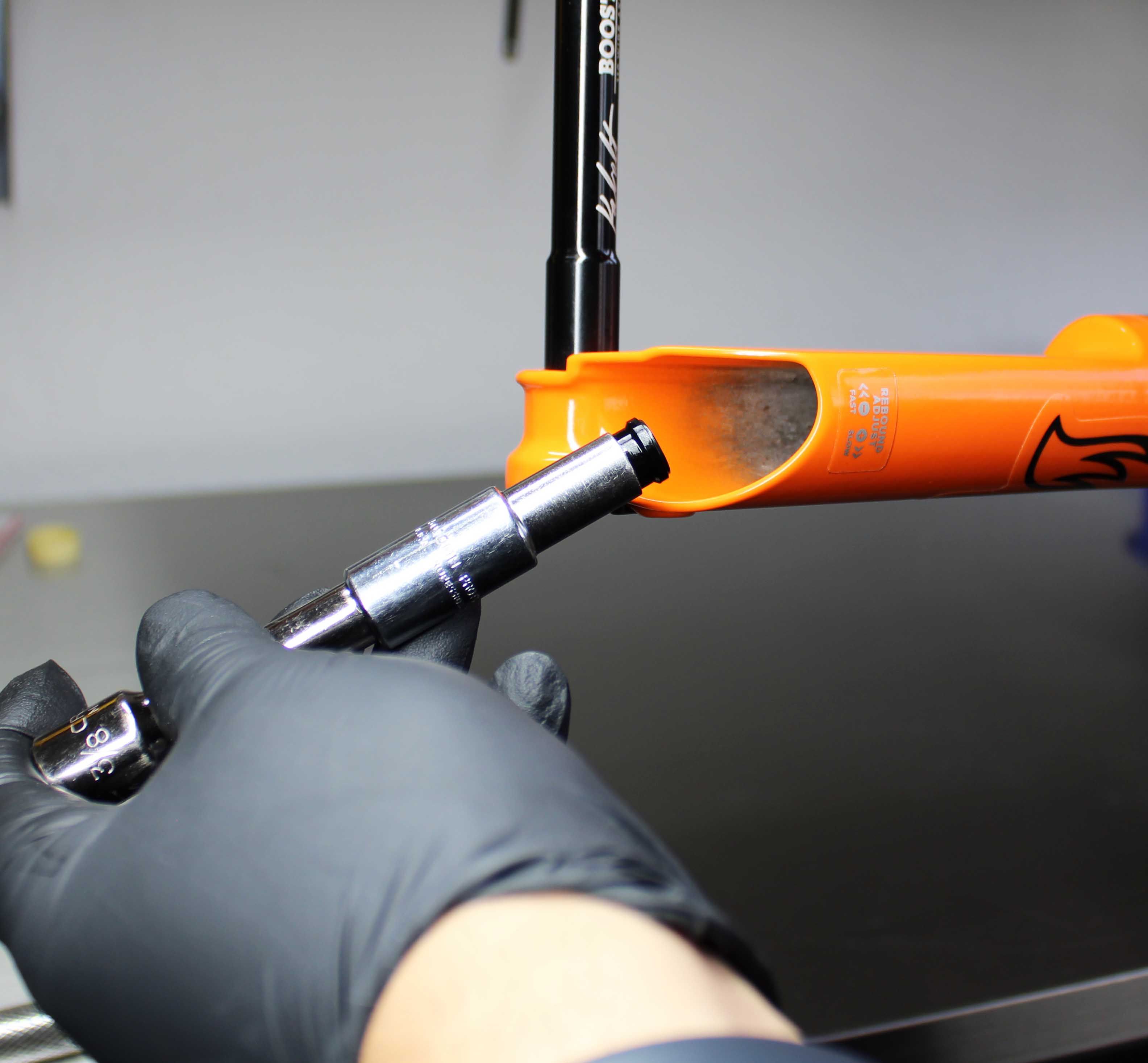
34mm-40mm: Use a 15mm socket to remove the damper side bottom nut. Make sure to remove and discard the orginal crushwasher which may be stuck to the bottom nut.

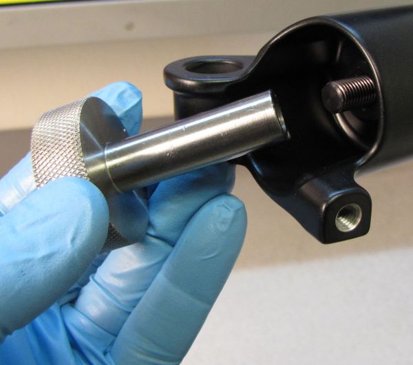
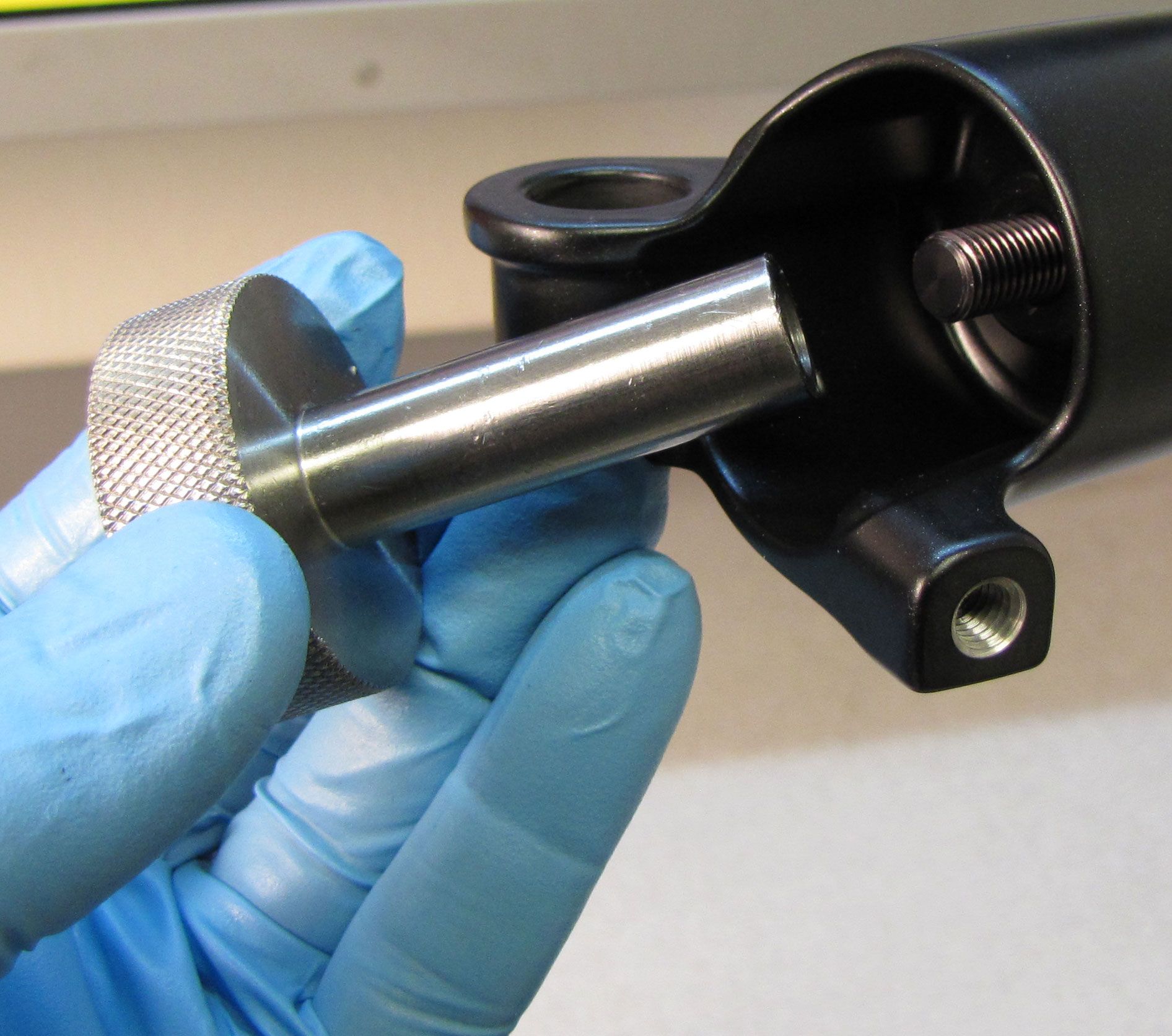
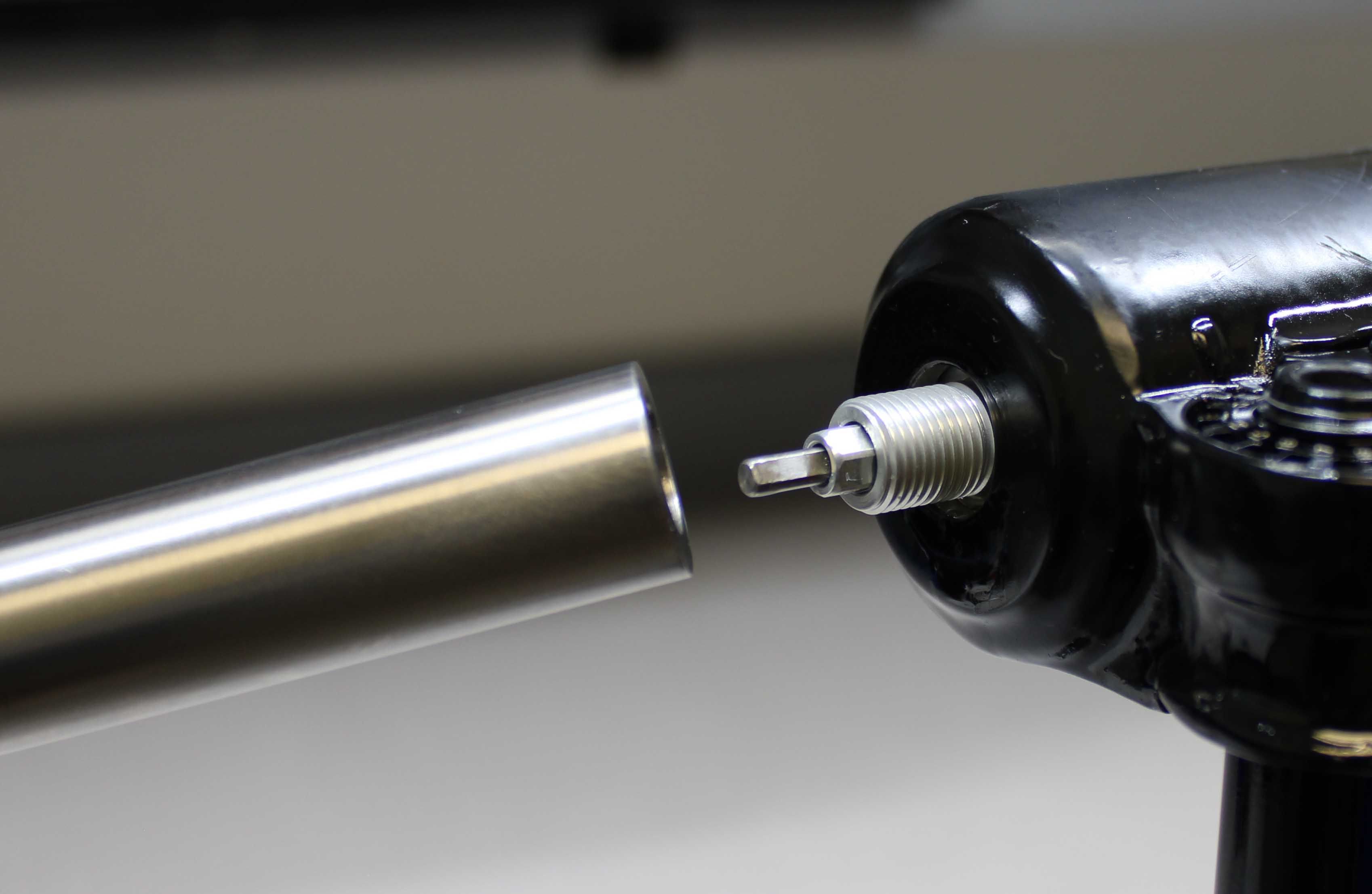
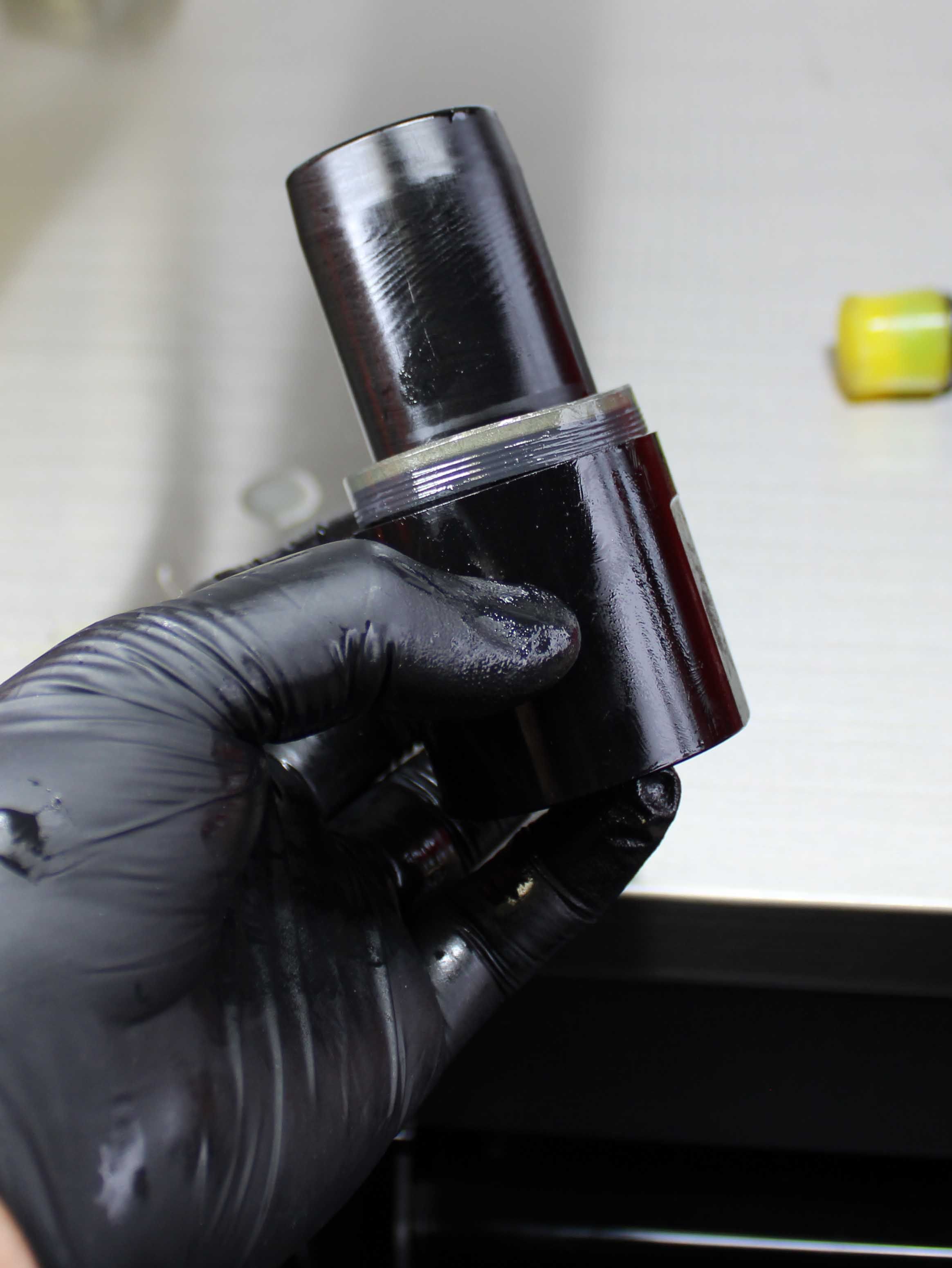
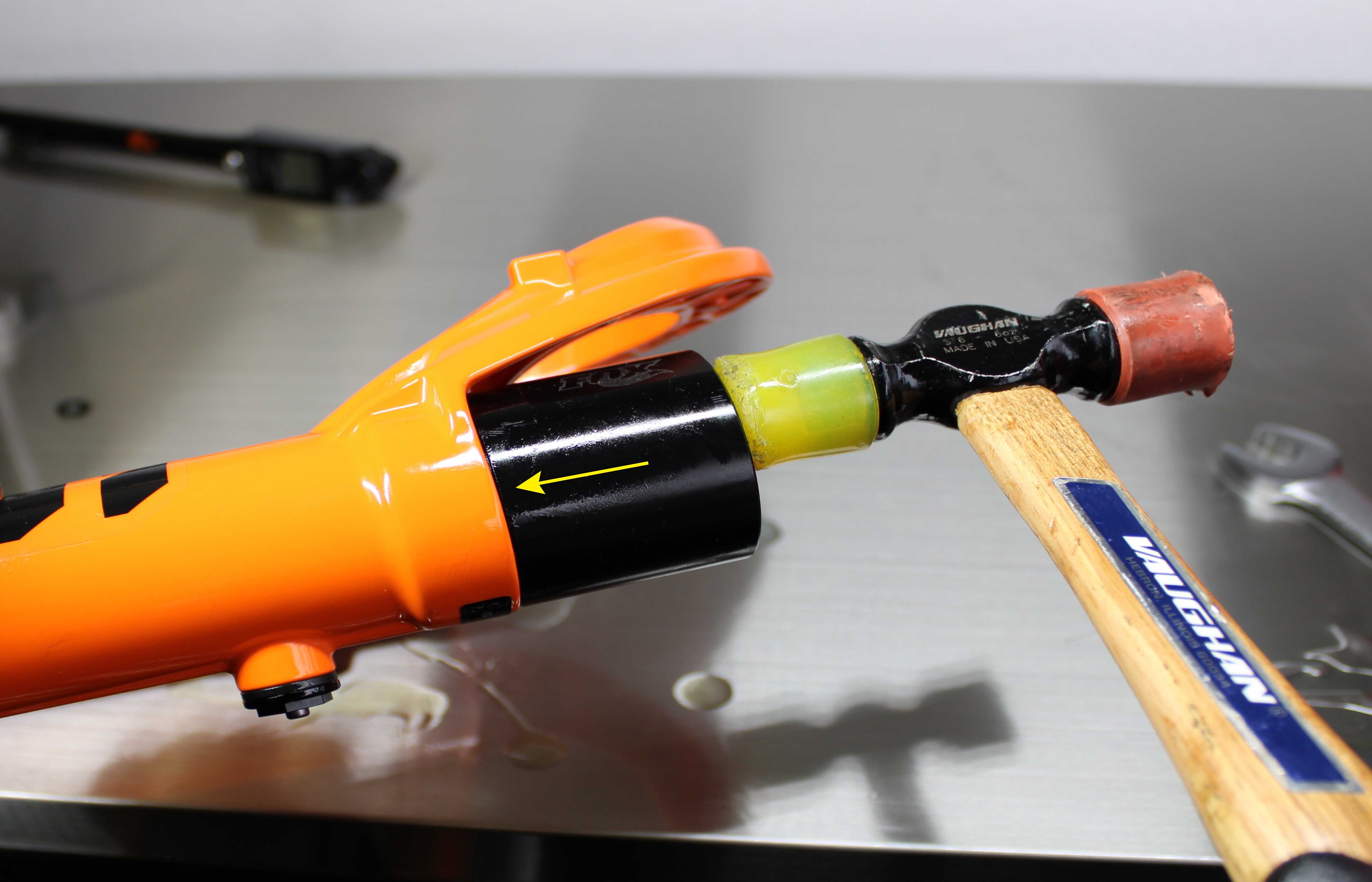
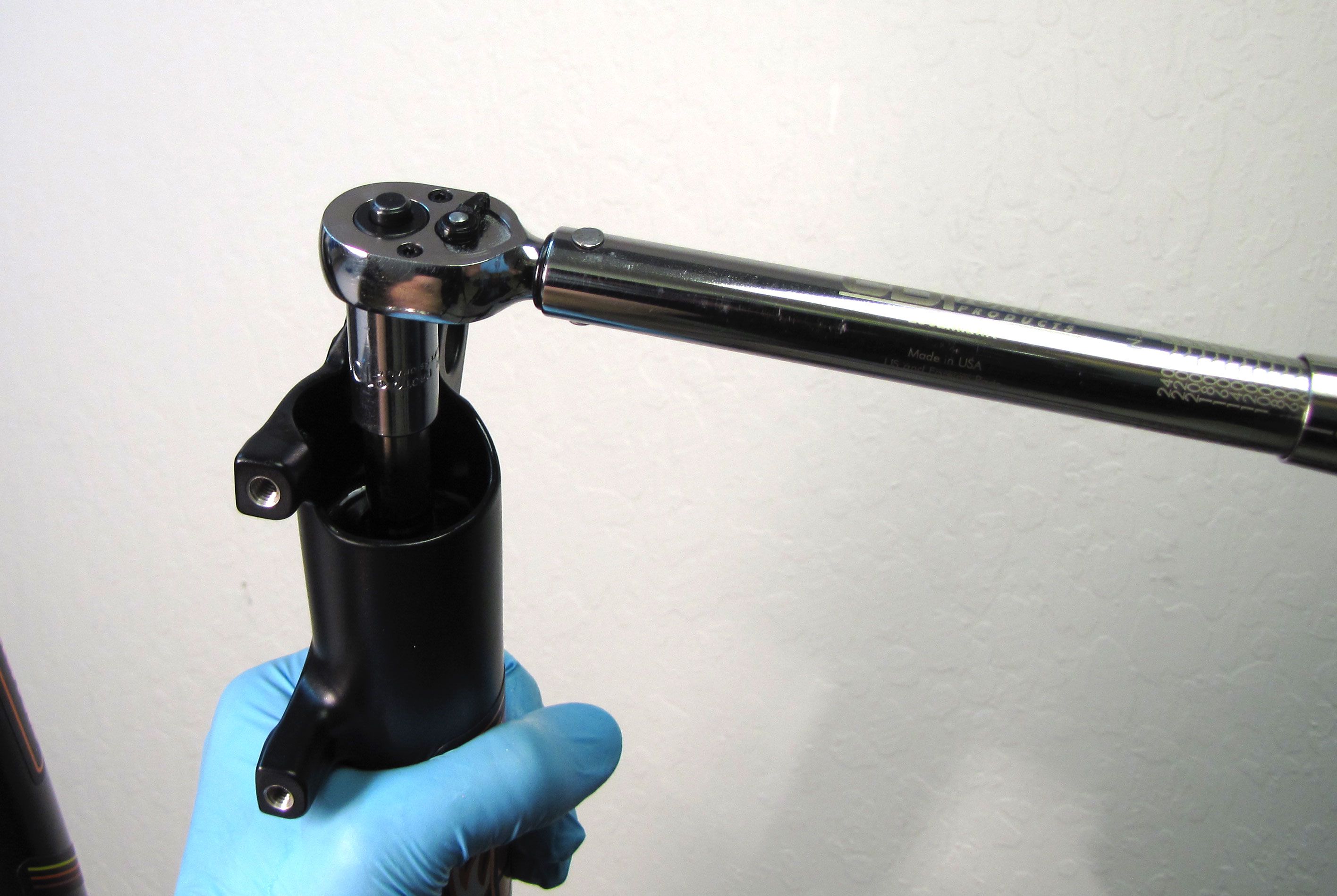
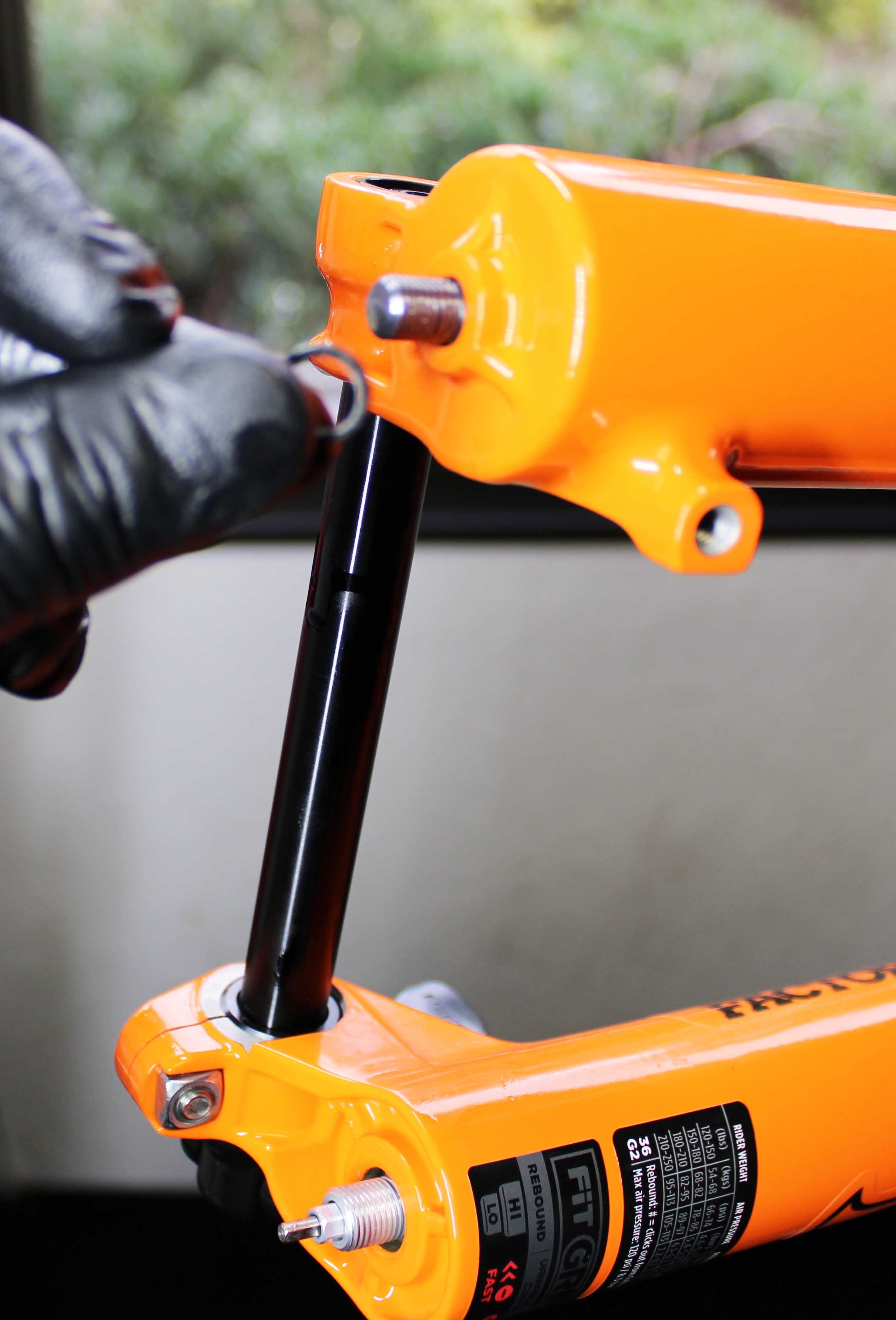
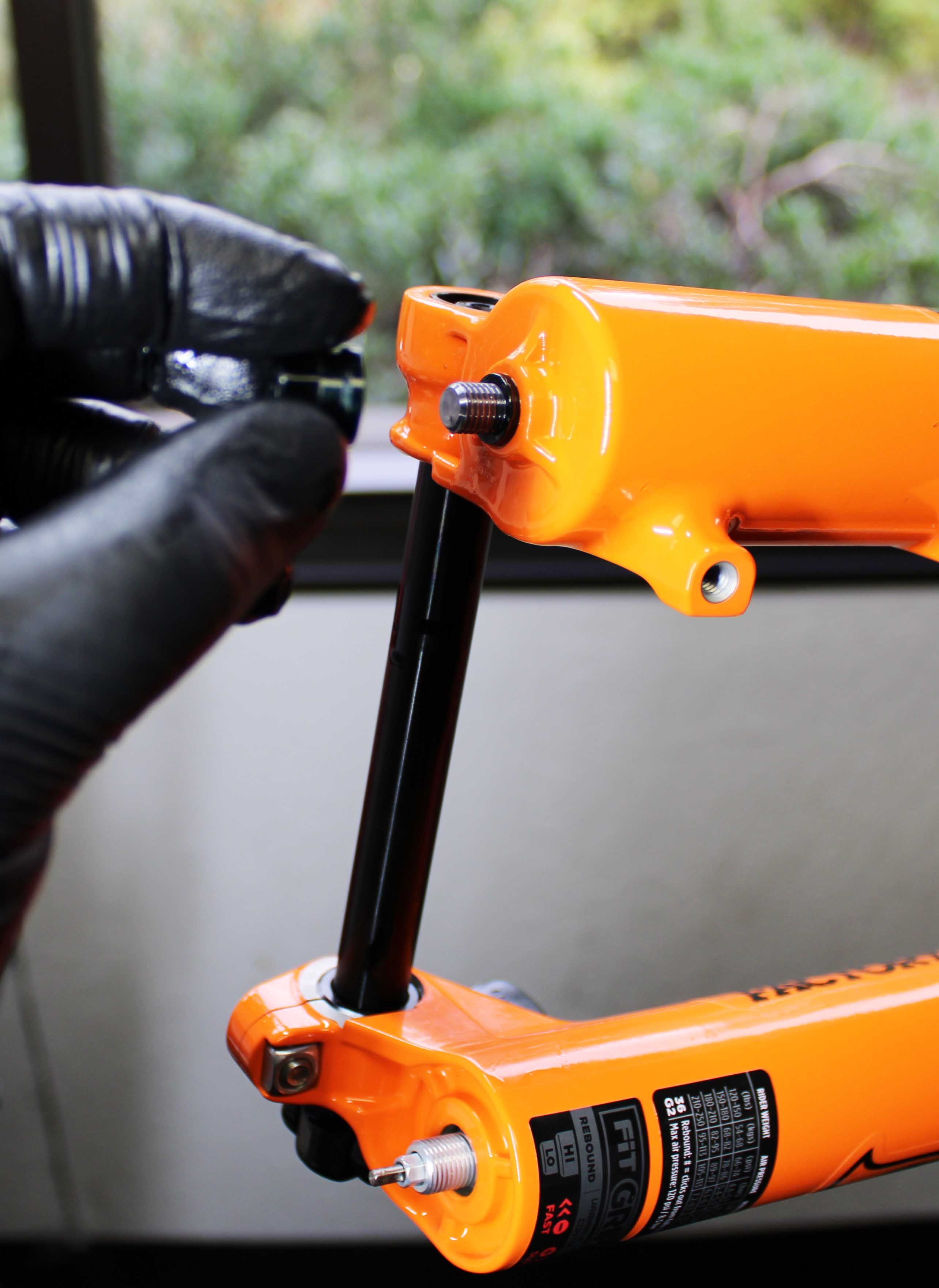
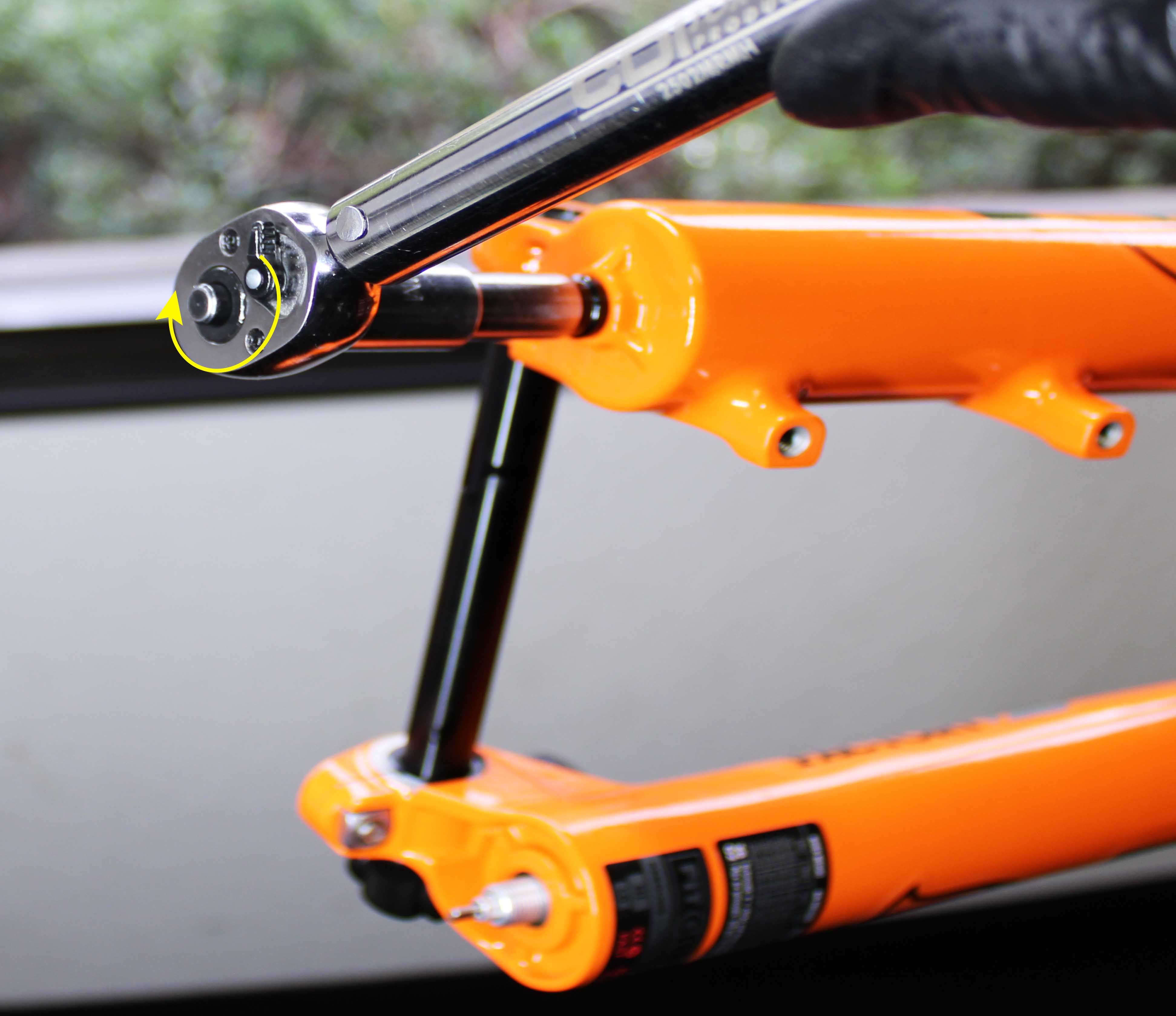
Step 5
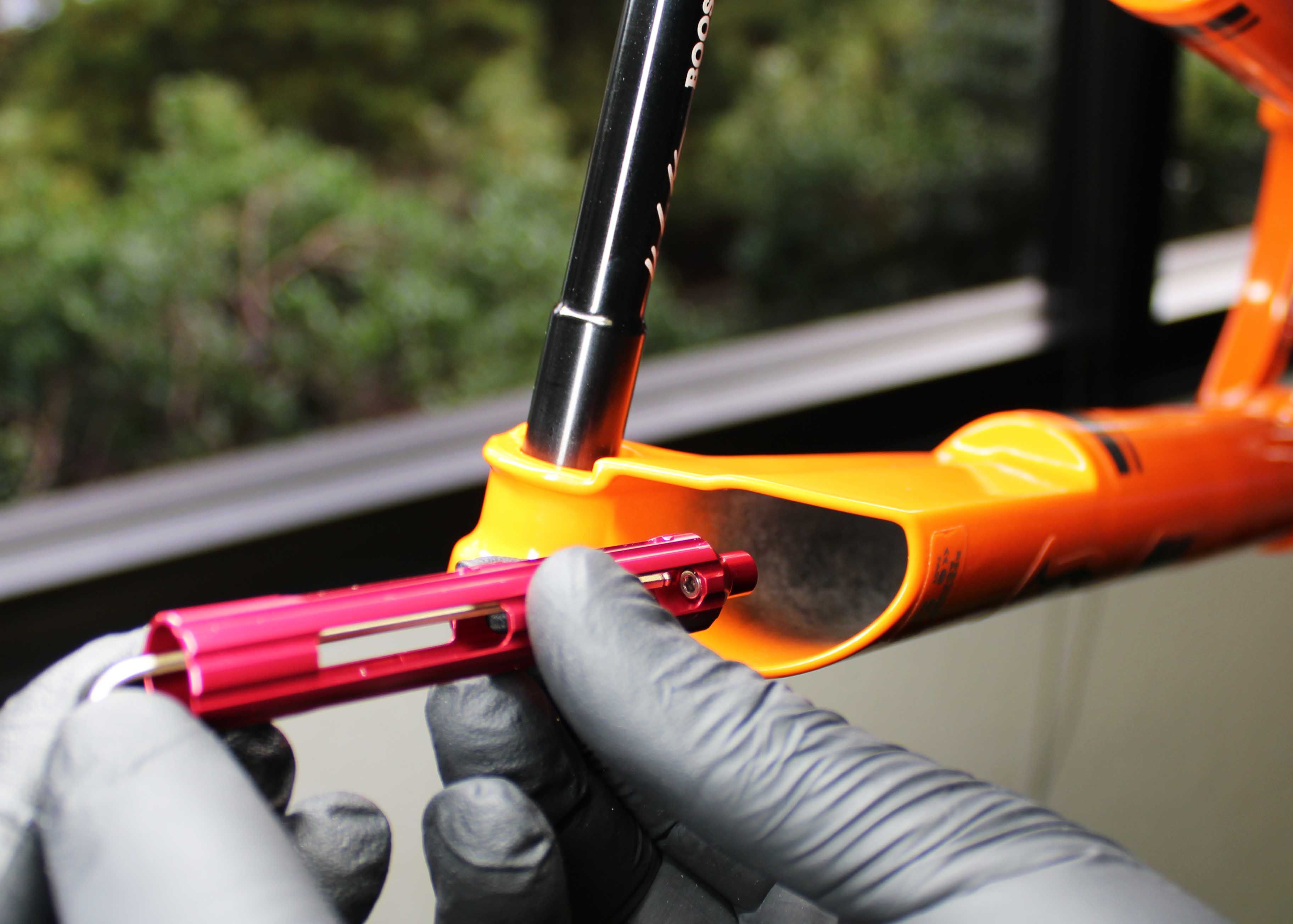
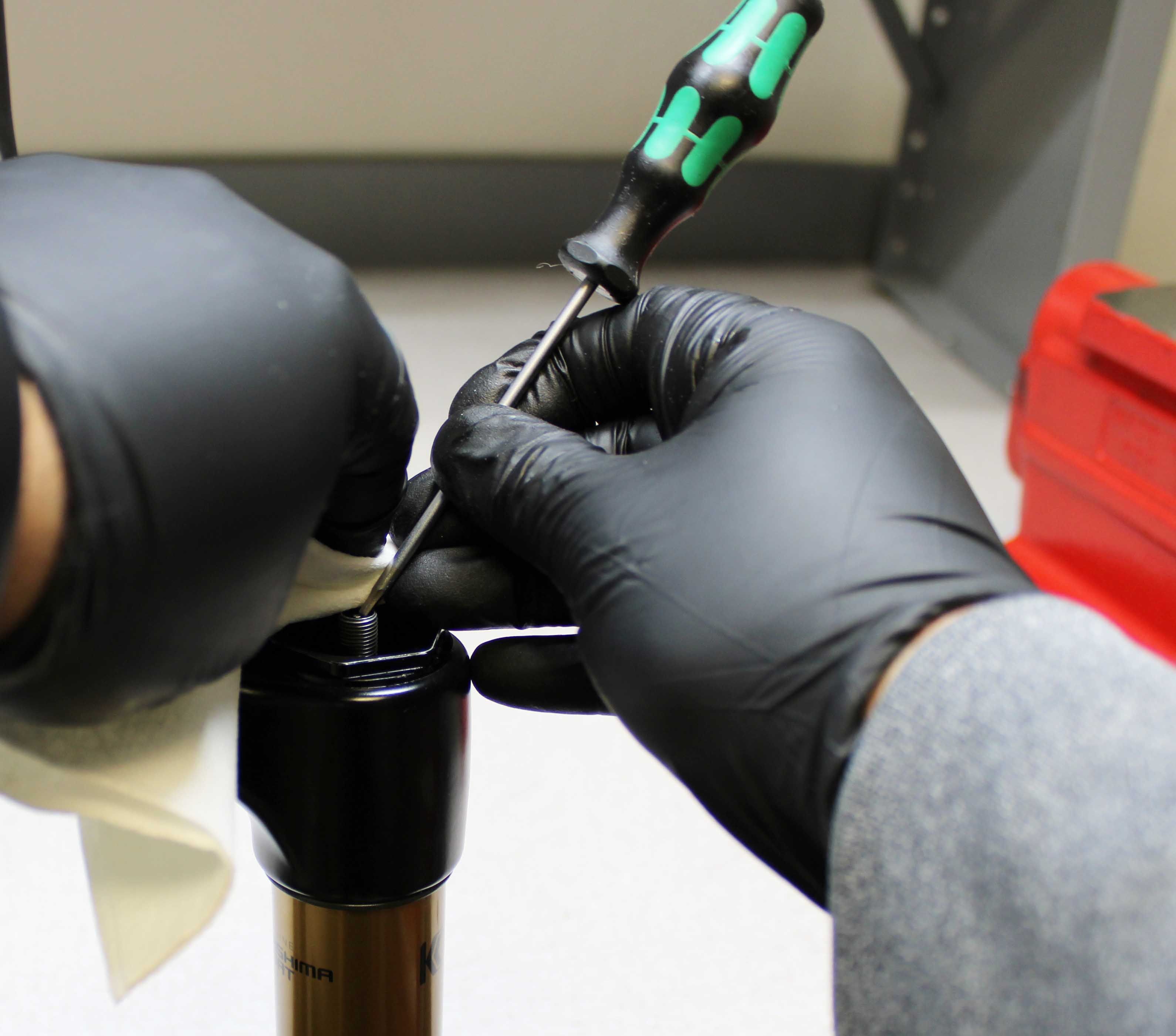
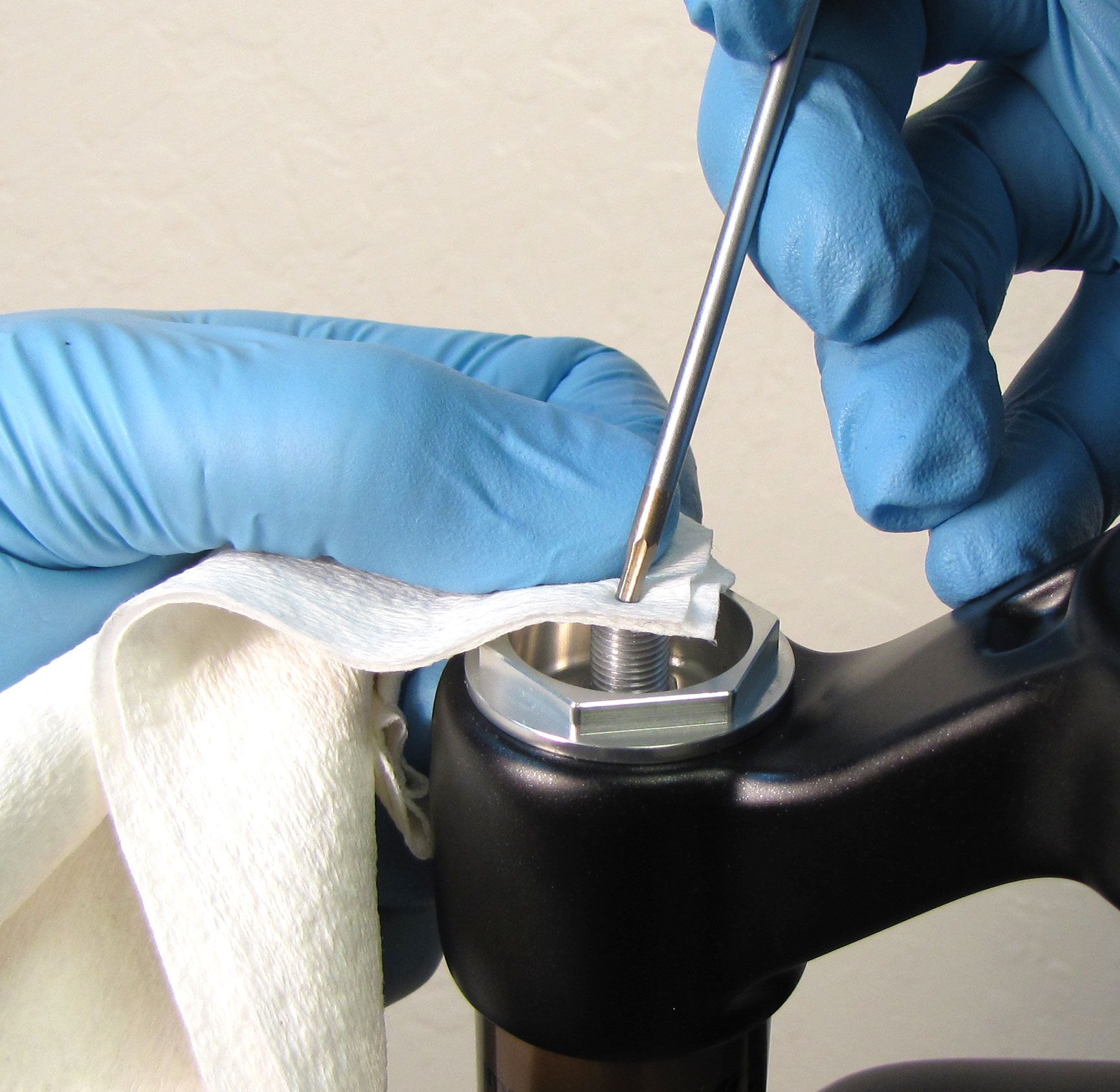
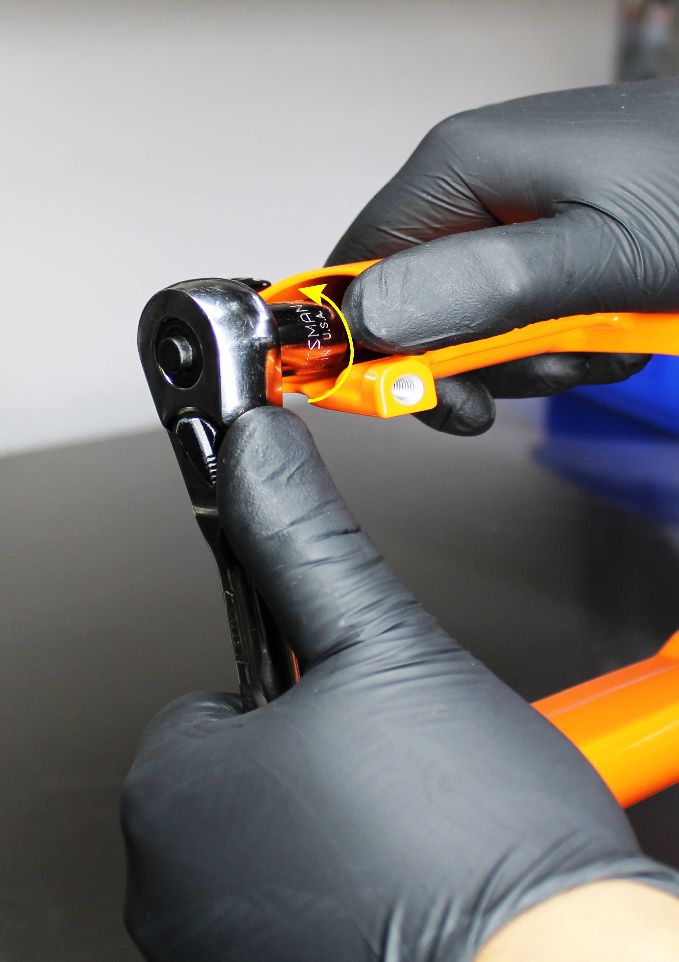
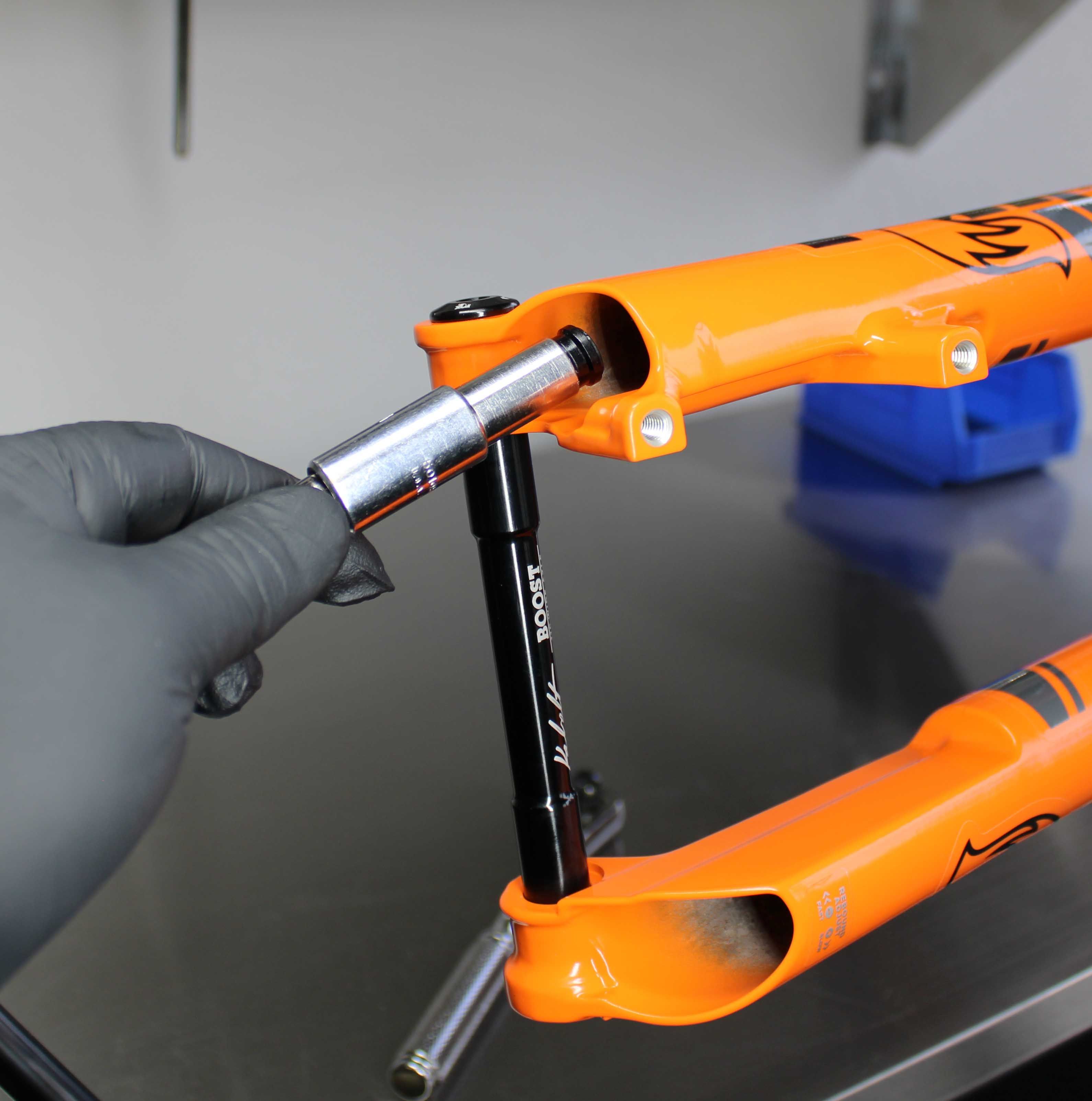
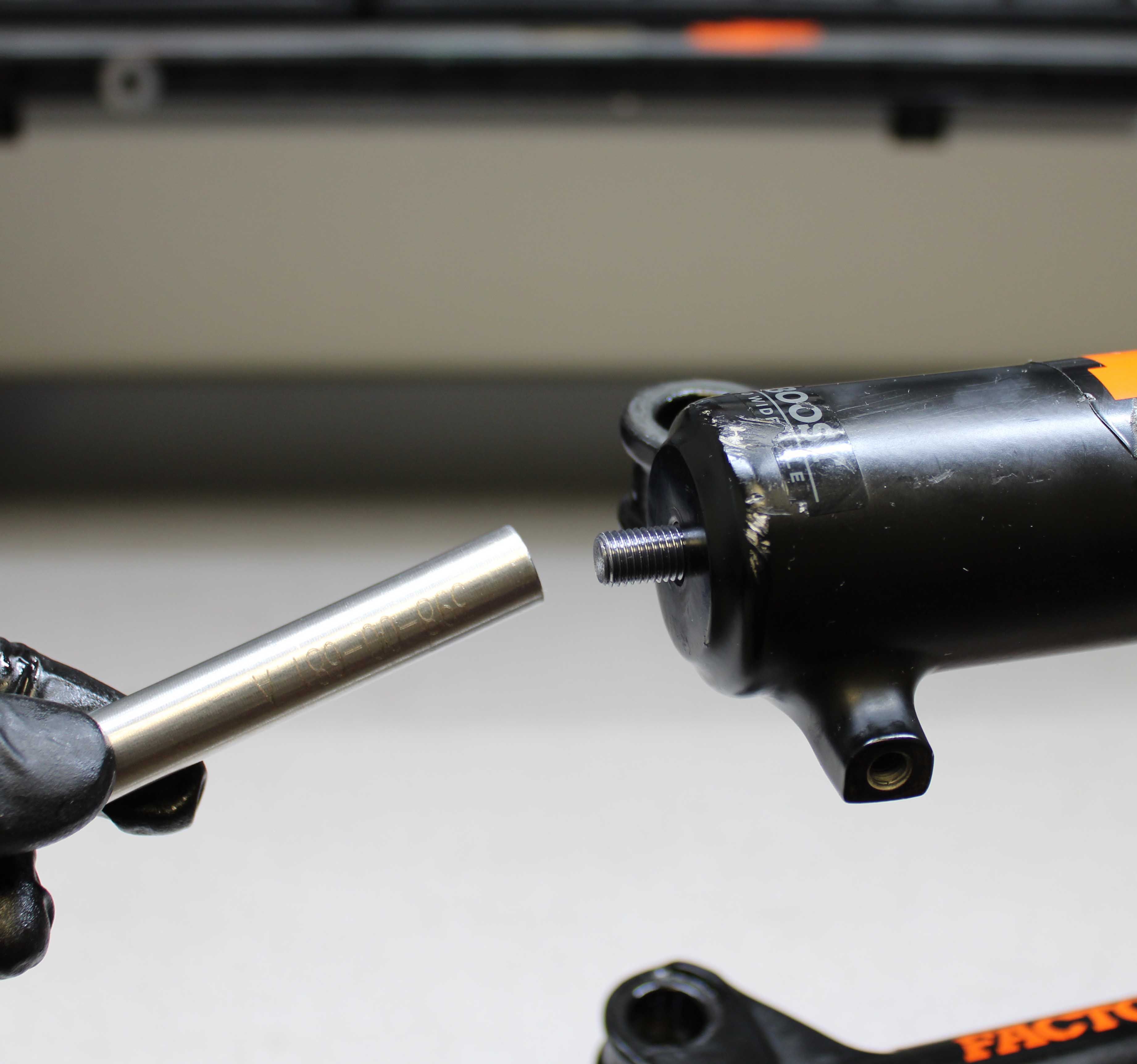
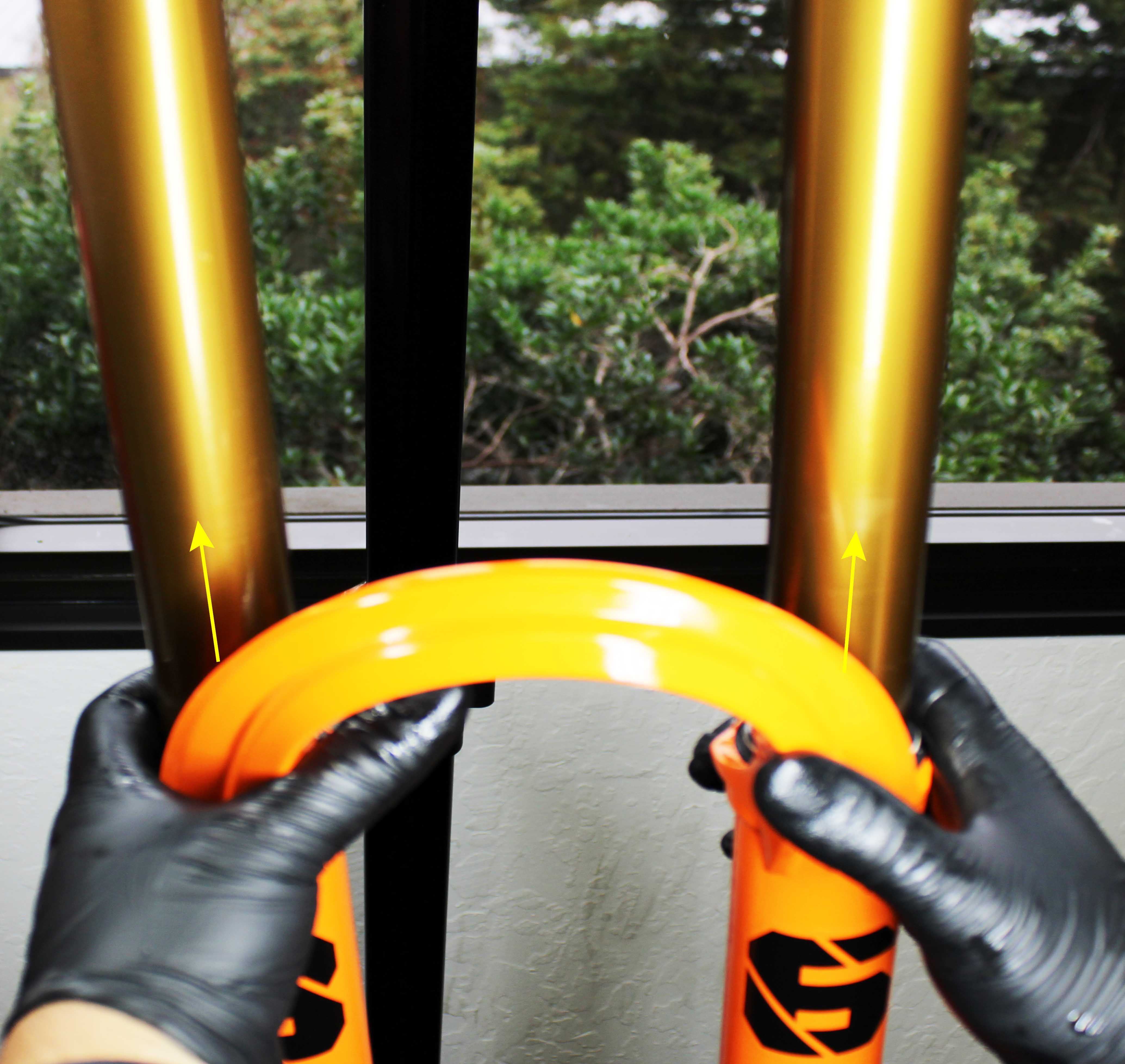
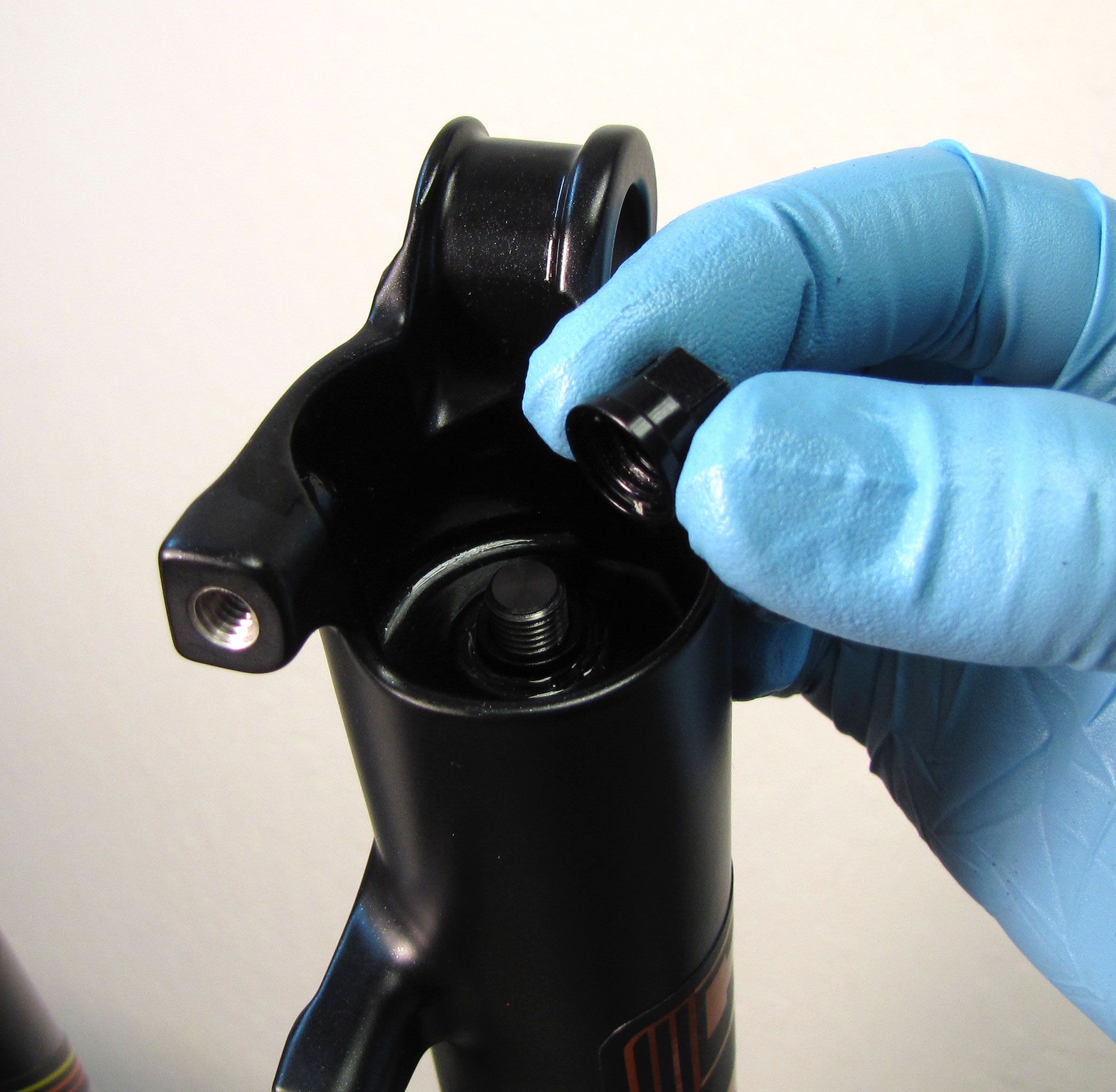
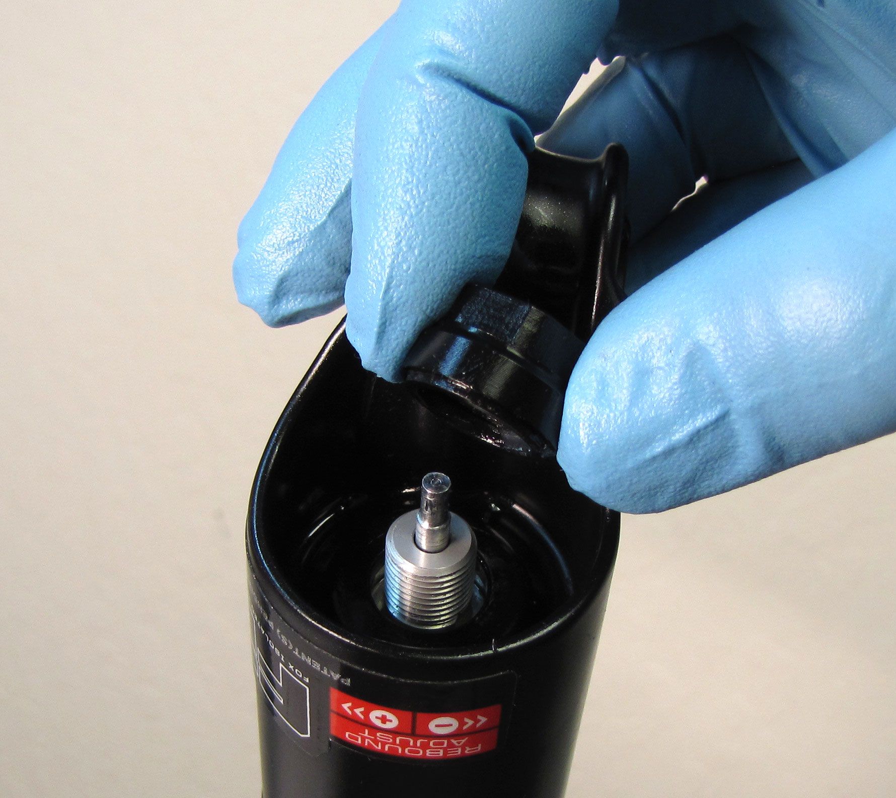
Use Damper Removal Tools 398-00-681 and 398-00-682 to dislodge the shafts from the lowers. Make sure that you have approximately half of the available threads engaged with your tool before striking with your mallet. Remove the damper removal tools, then bring the fork upright over an oil basin to drain. After oil stops draining from the lowers, pull the lowers off of the upper tubes and set them aside.
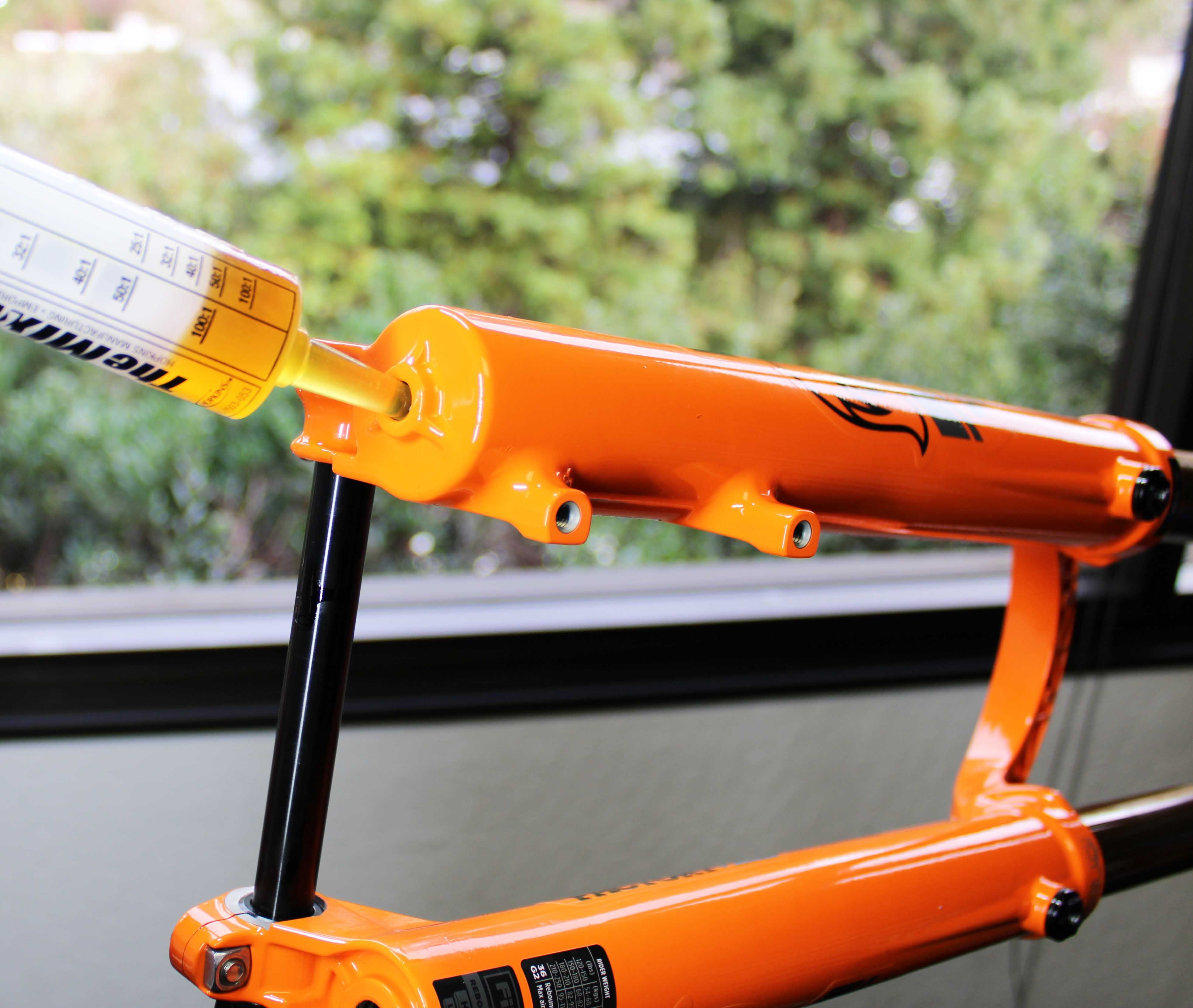
Step 6
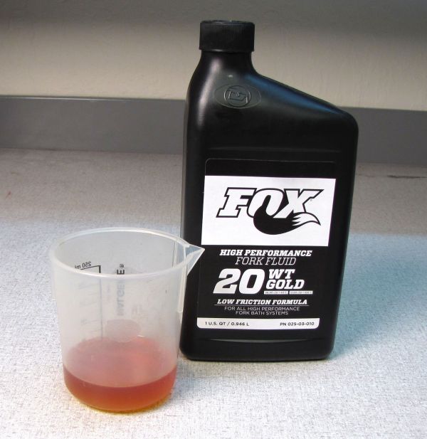
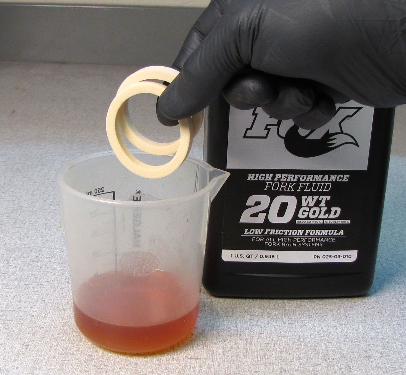
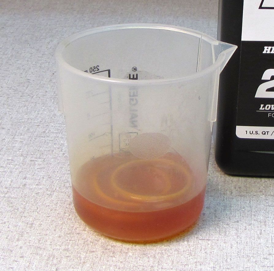
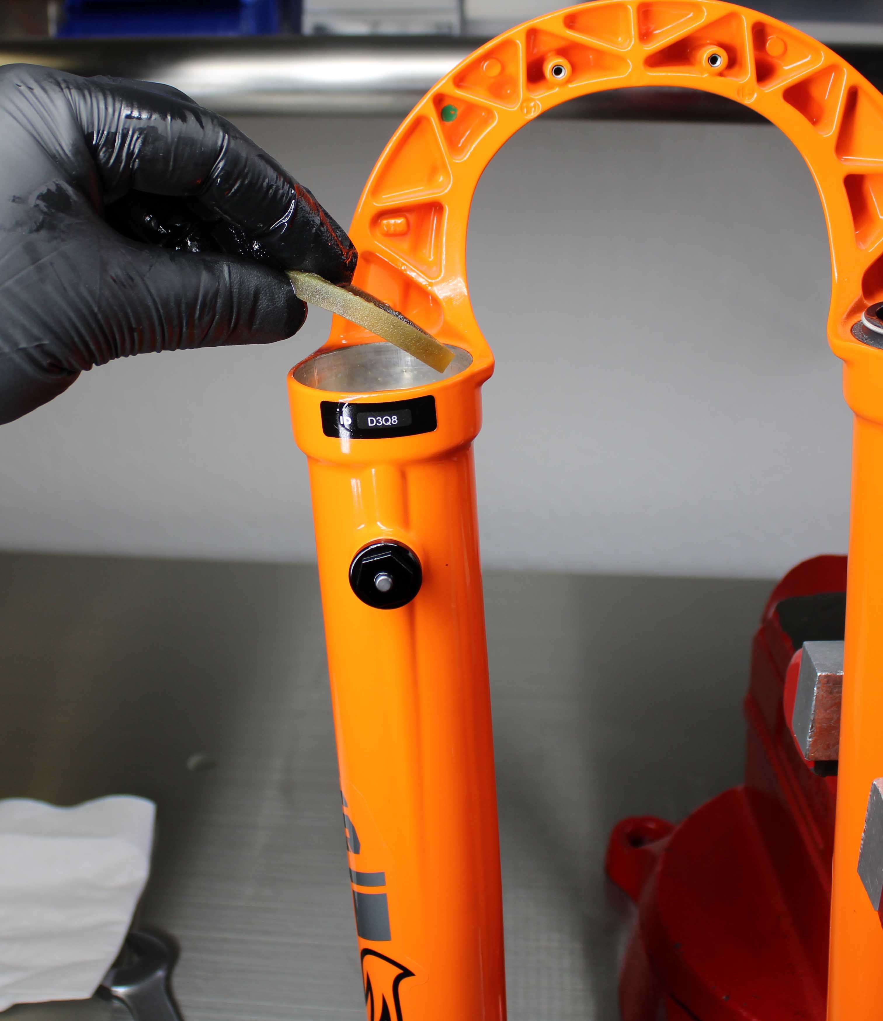
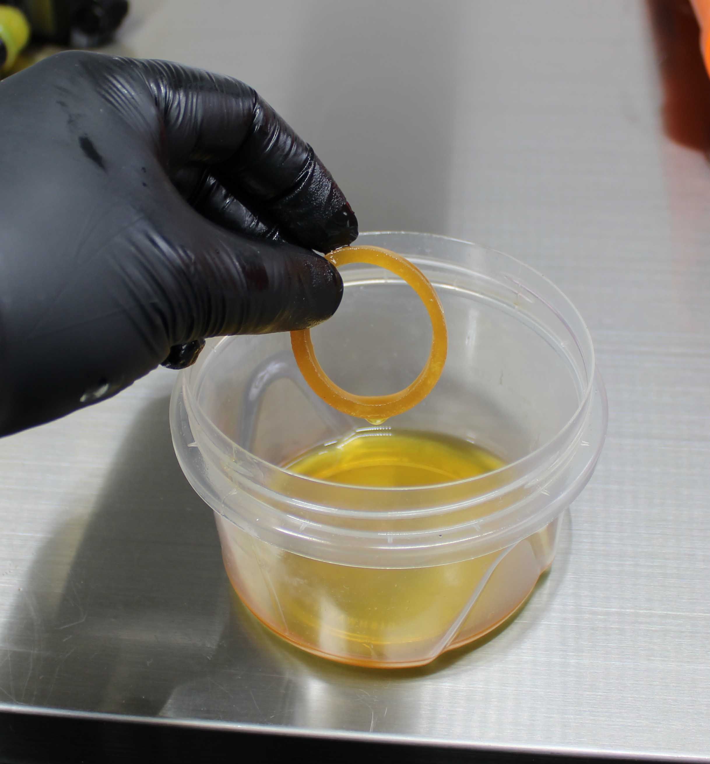
Soak the new foam rings from the Dust Wiper kit in a small cup of FOX 20wt. Gold bath oil.


Step 7
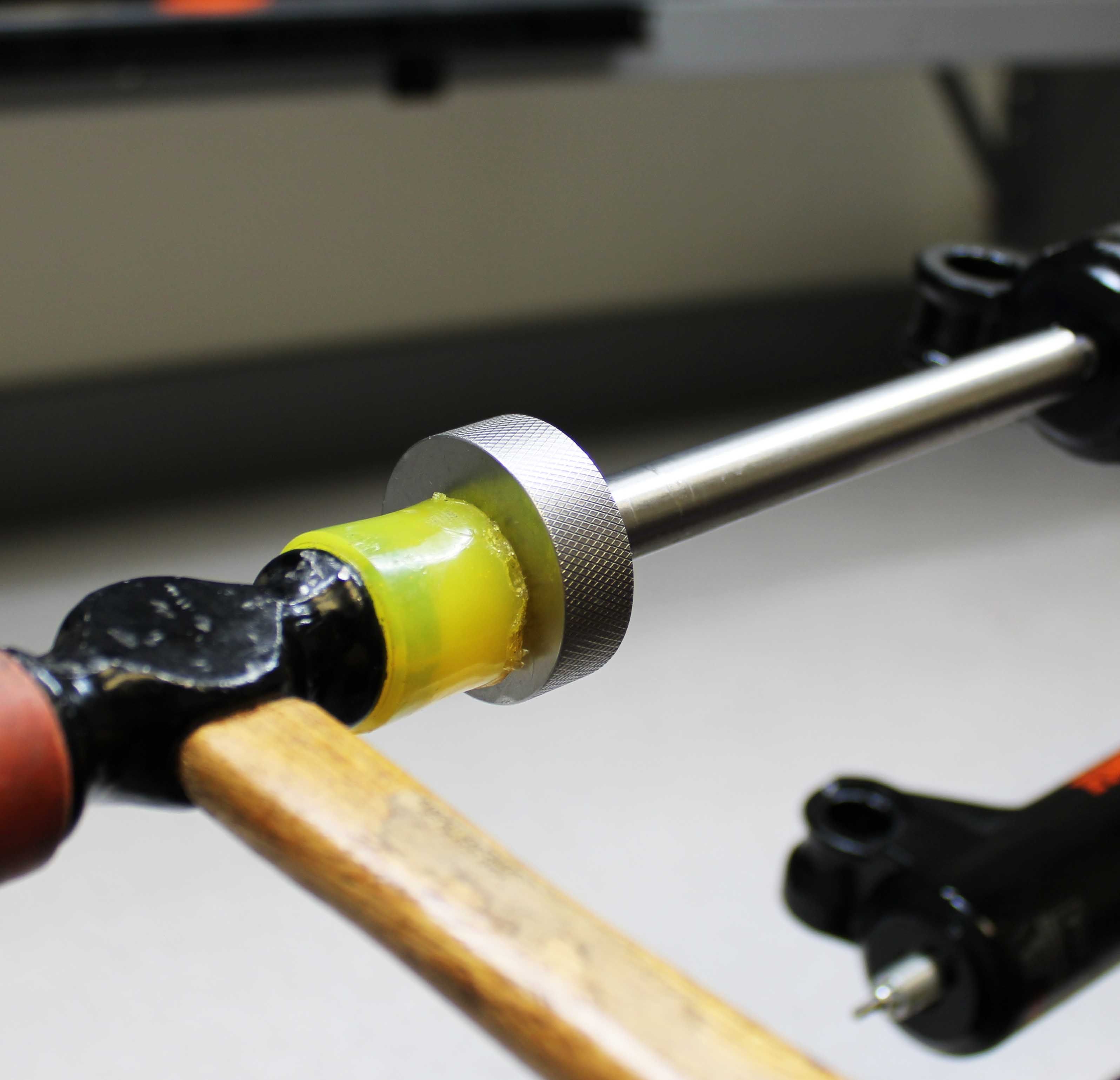
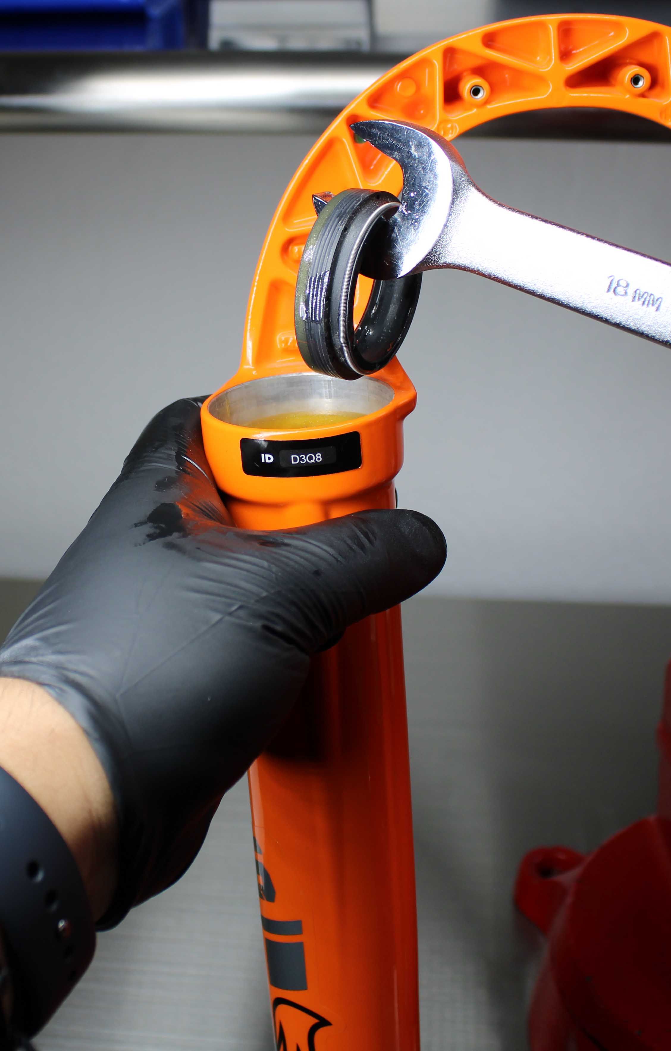
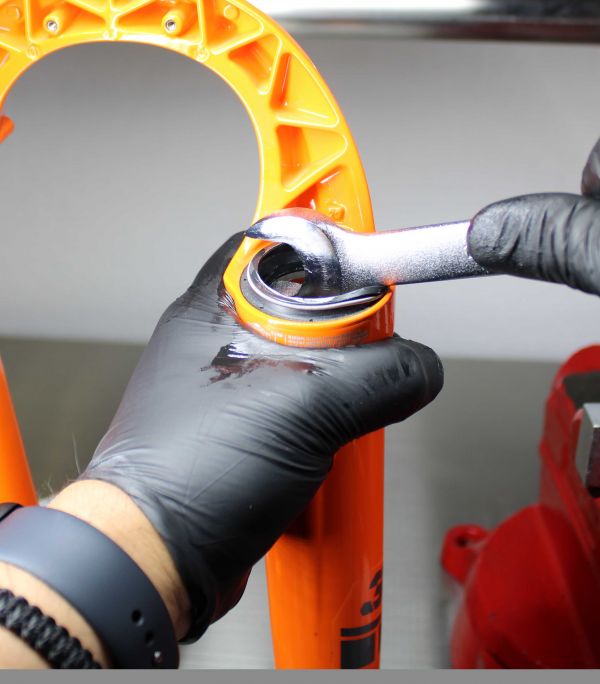
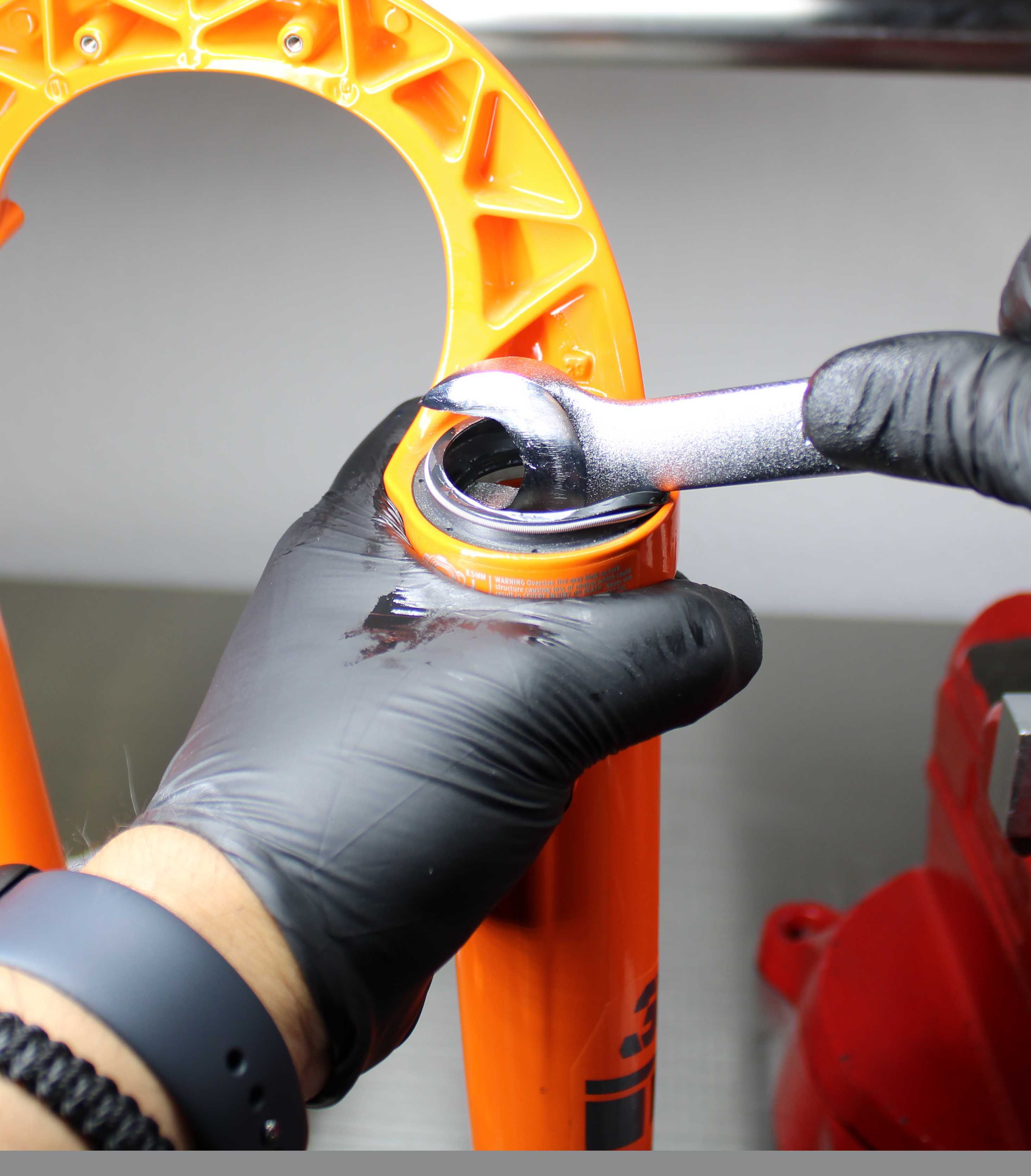
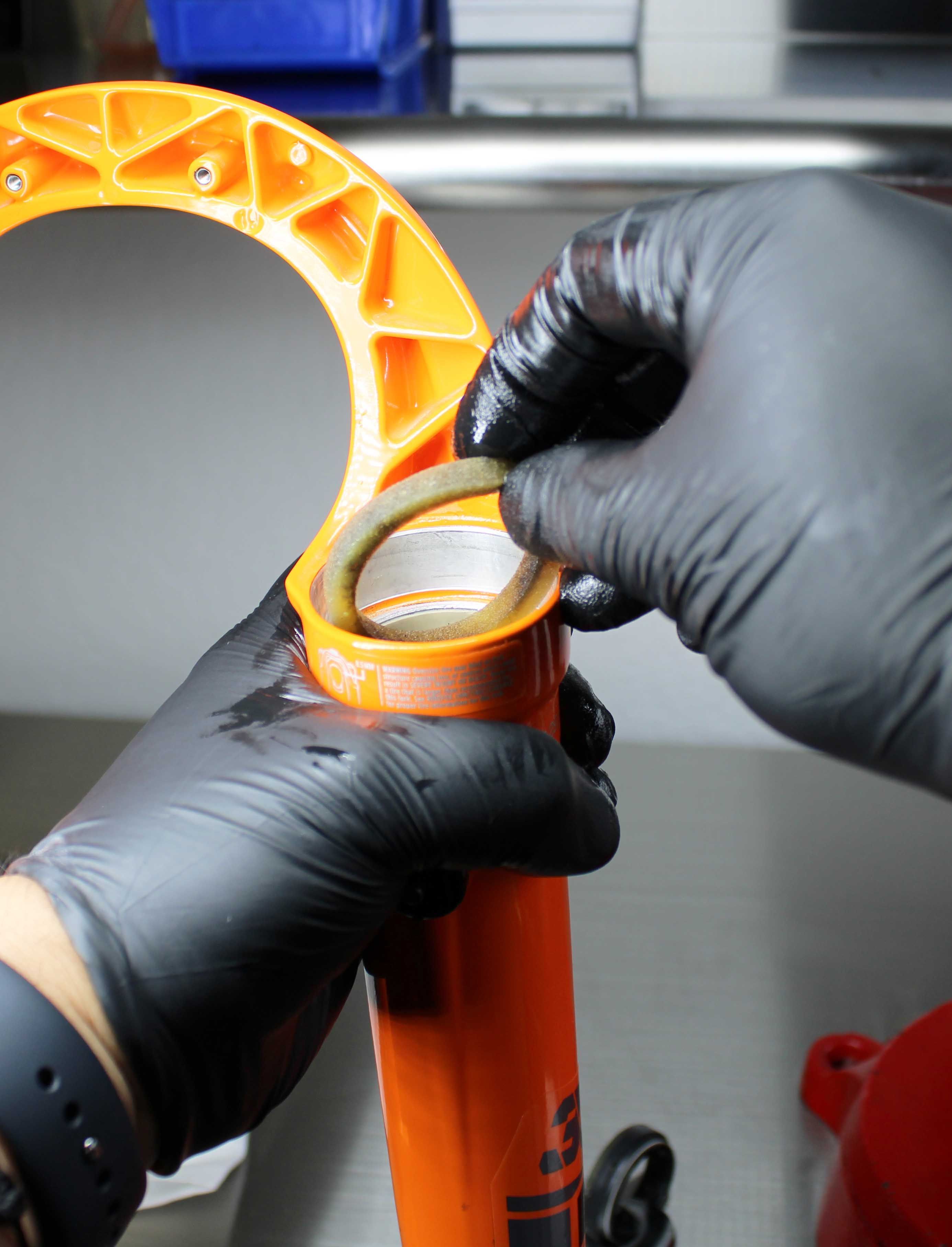
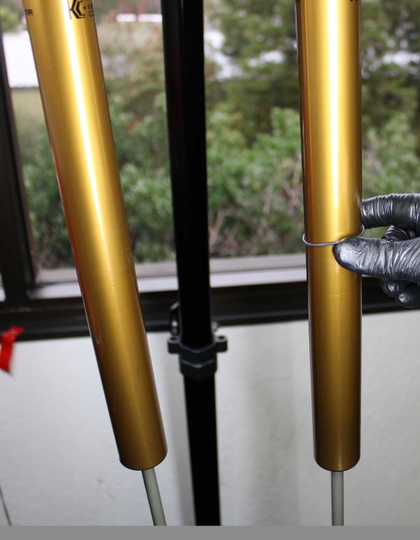
Using a wooden or plastic dowel is the recommended method for removing the dust wipers and foam rings. If you choose to use a wrench or other metallic tool, use extra caution not to scratch the inner wall of the magnesium lower leg, as you lever out the dust wiper. Do this by making sure the tip of your metallic tool is cushioned from the magnesium lower leg by the foam ring, just below the dust wiper.
Step 8
Repeat the process on the other side. Discard the original foam rings and dust wipers as they are not reusable once removed due to potential distortion.


Step 9
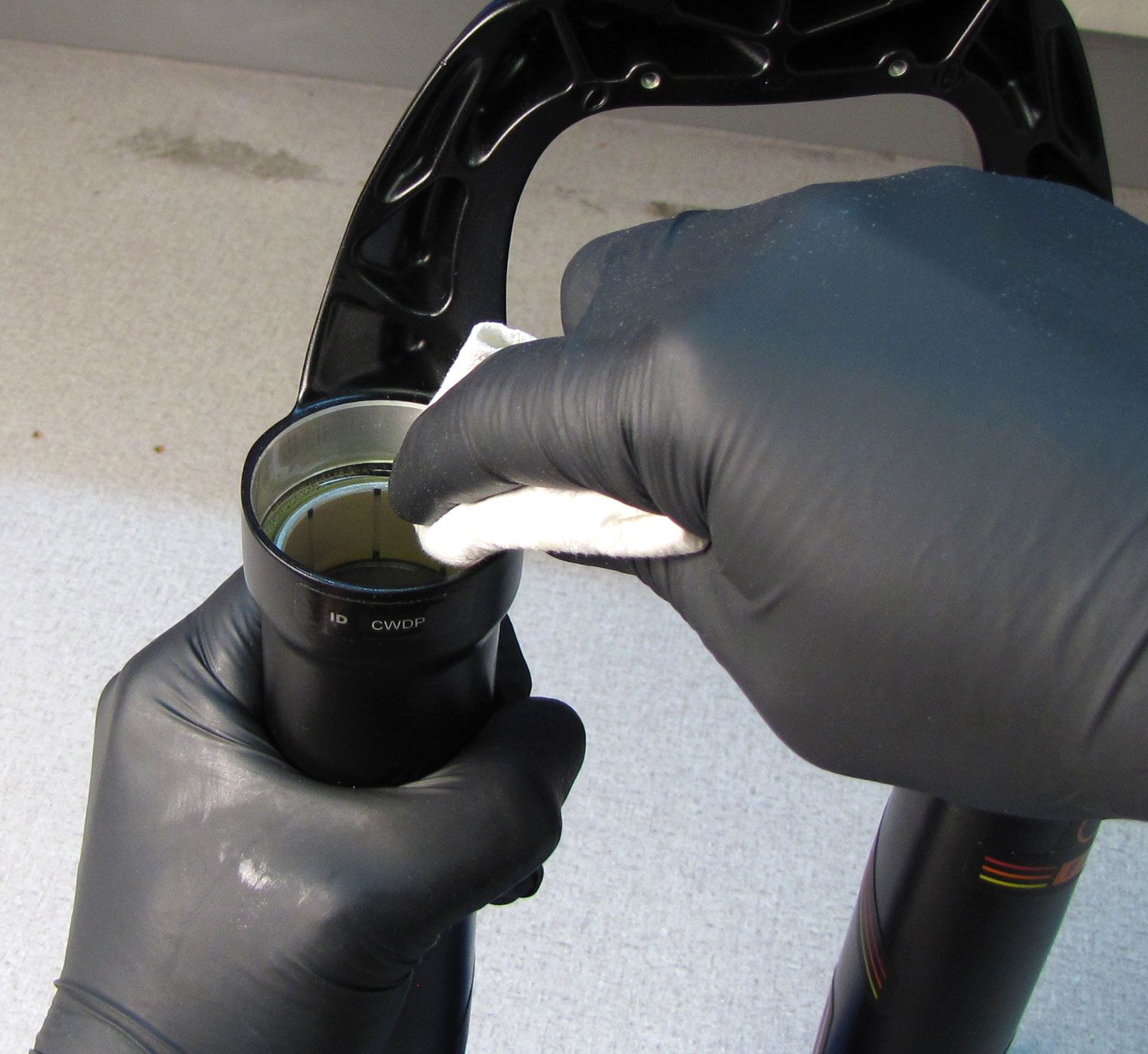
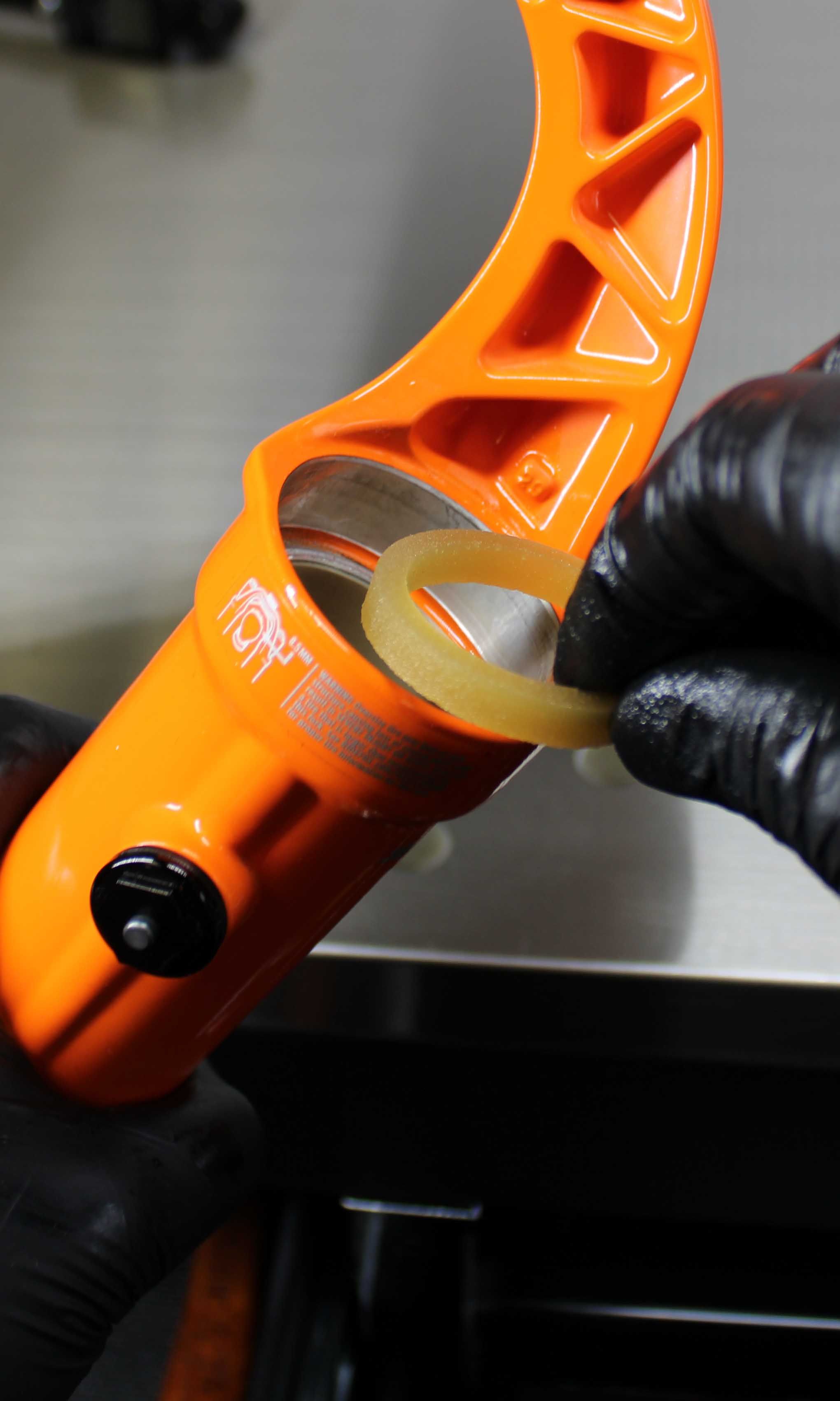
Thoroughly clean the seal bore and the inside of the lower legs with warm soapy water or Isopropyl alcohol. Blow the lowers dry with clean compressed air. Install new foam rings soaked in FOX 20wt. Gold Oil.
Step 10
Use a small amount of FOX 20wt. Gold oil to coat the outside ribs and exposed metal base of the new dust wiper. Rest the oiled wiper onto the seal driver.


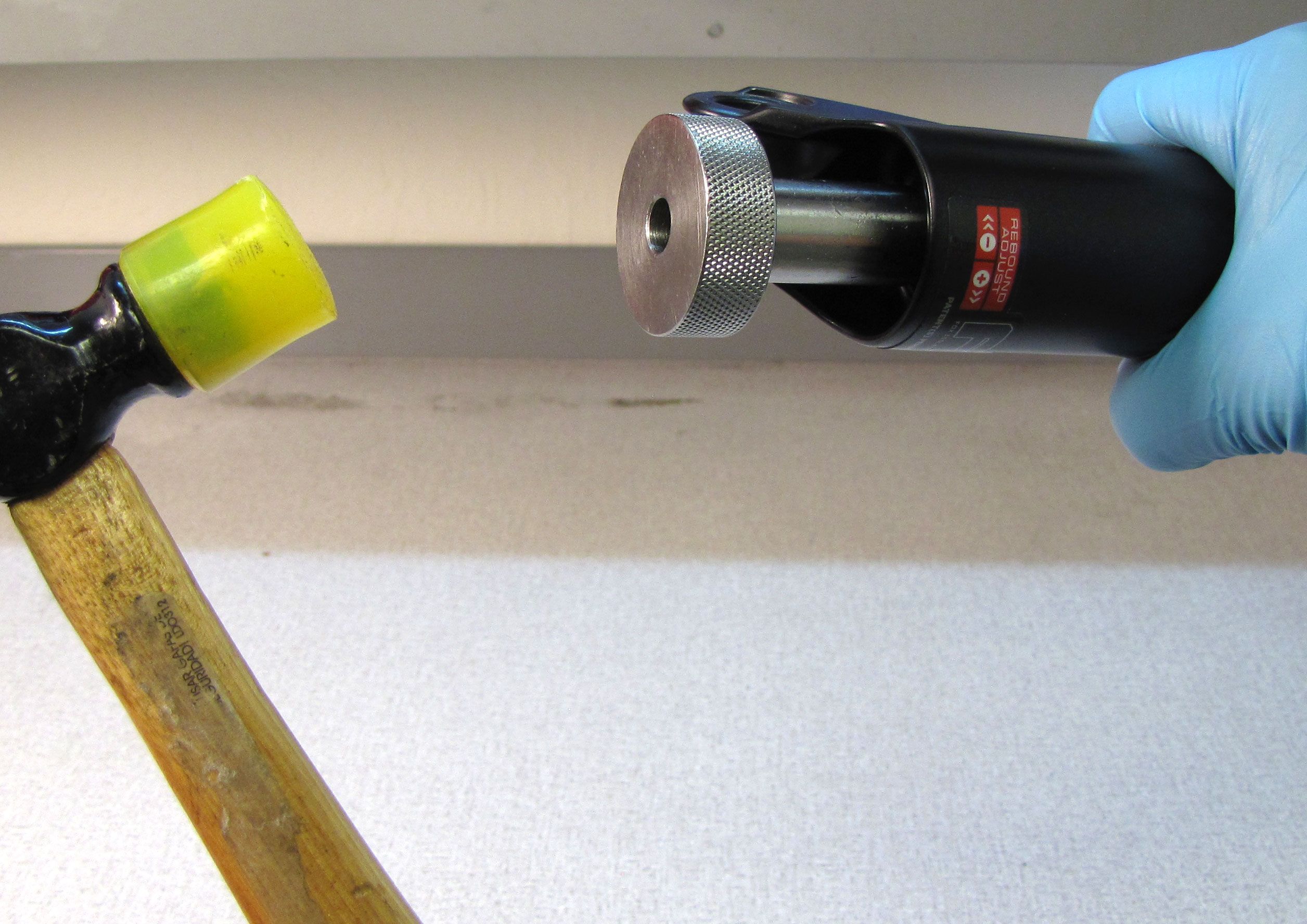
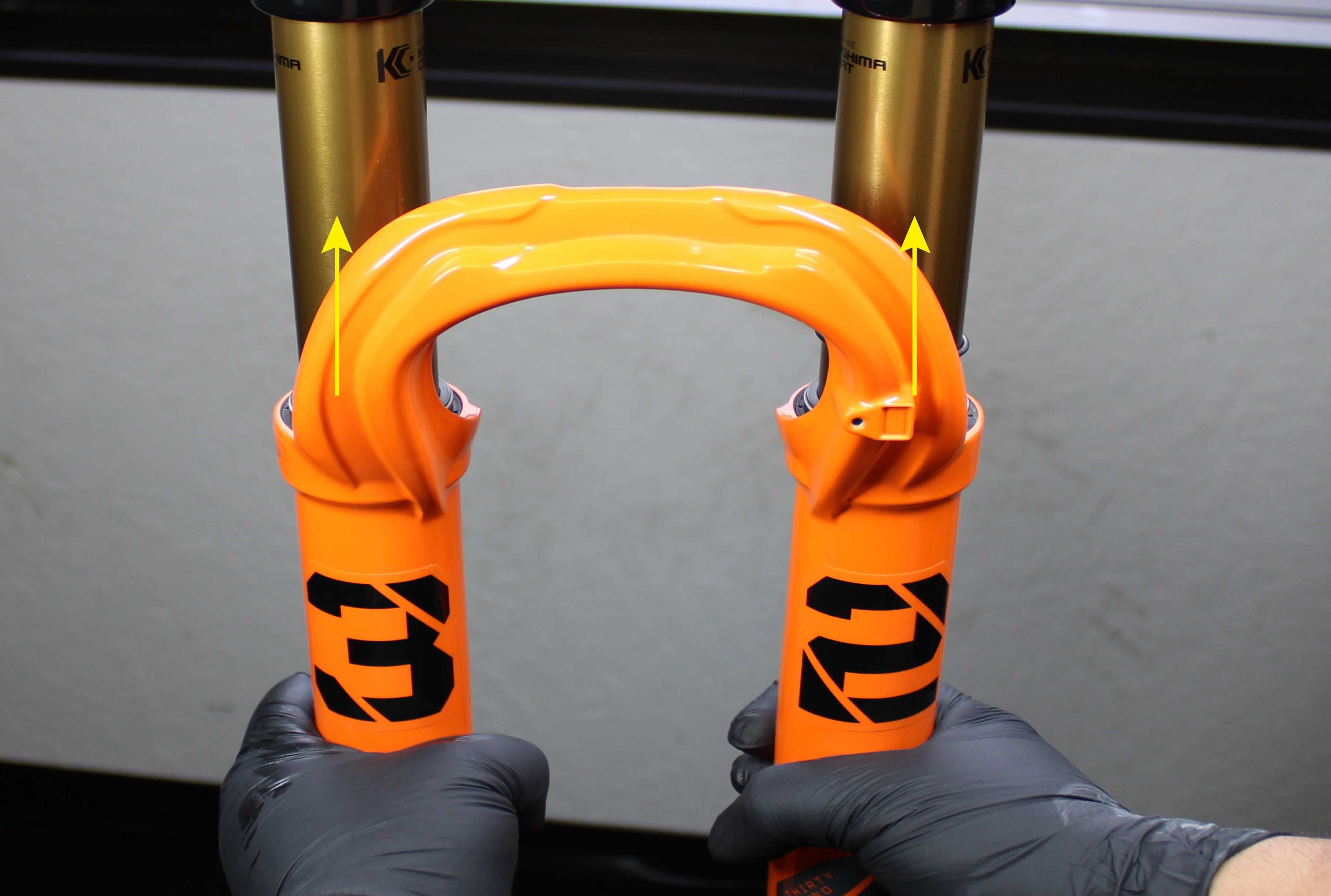
Step 11
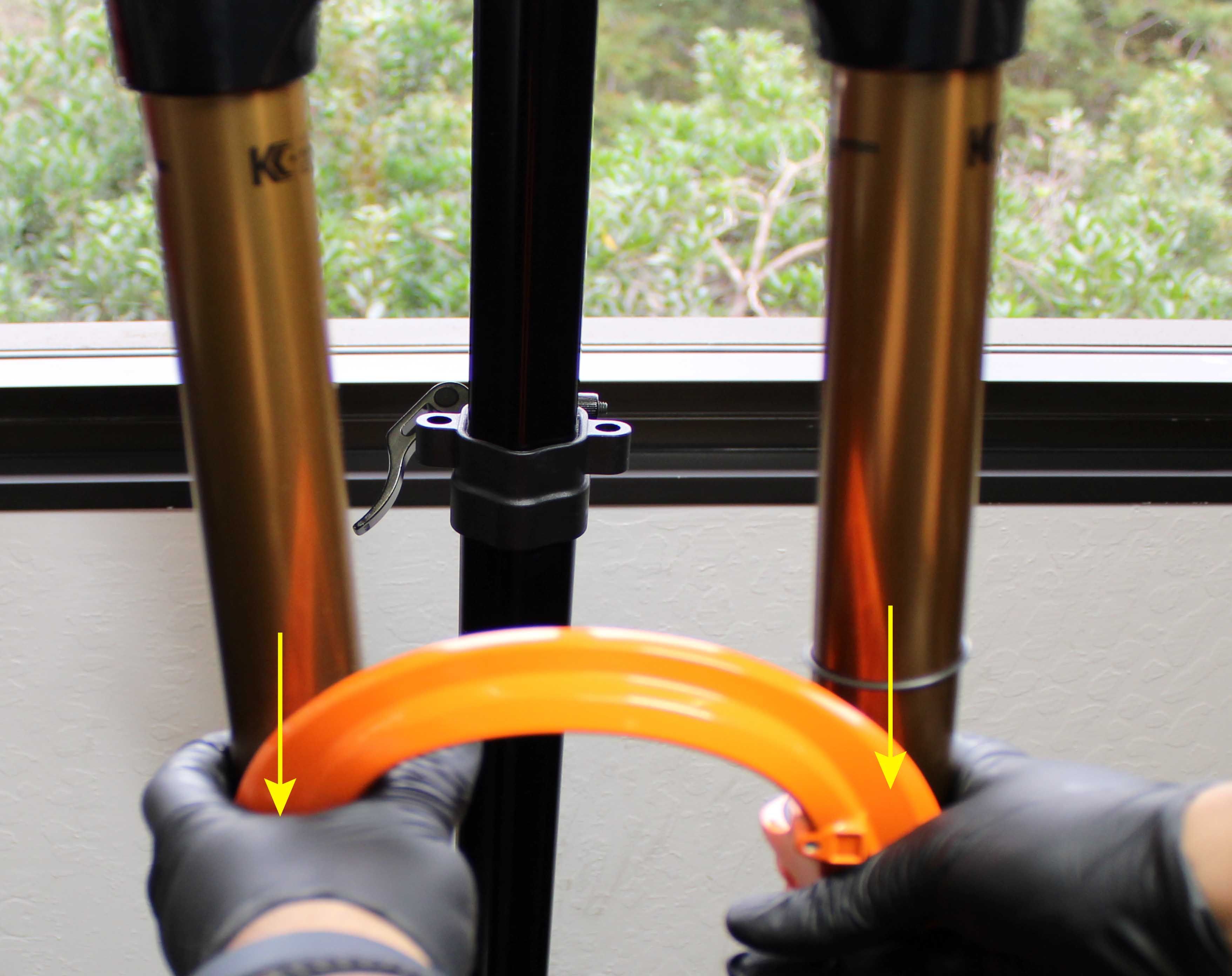
While holding the lower leg driver straight and level, tap the driver with a plastic faced mallet until the wiper is flush with the edges of the seal bore. Repeat on other side.
Step 12
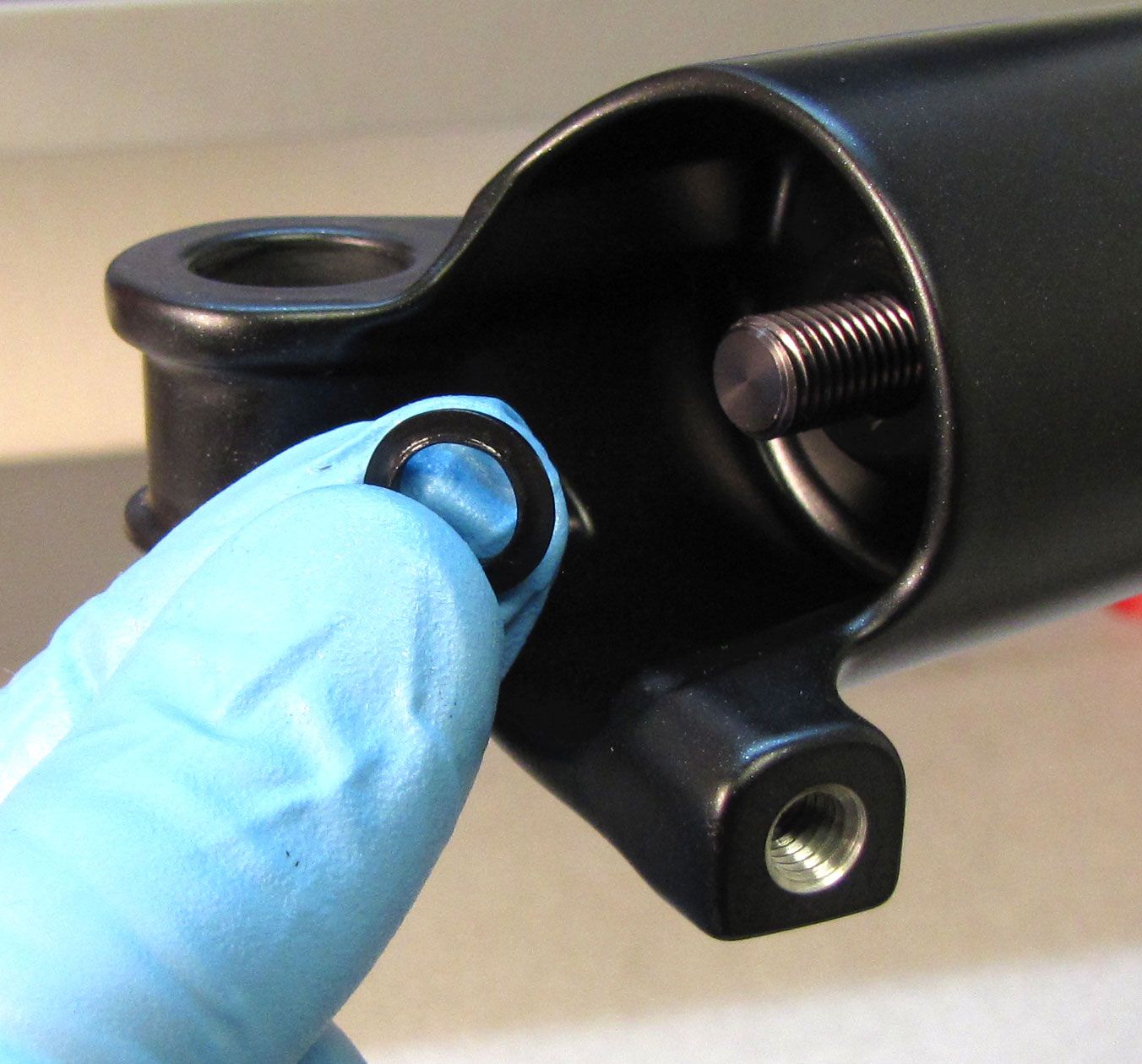
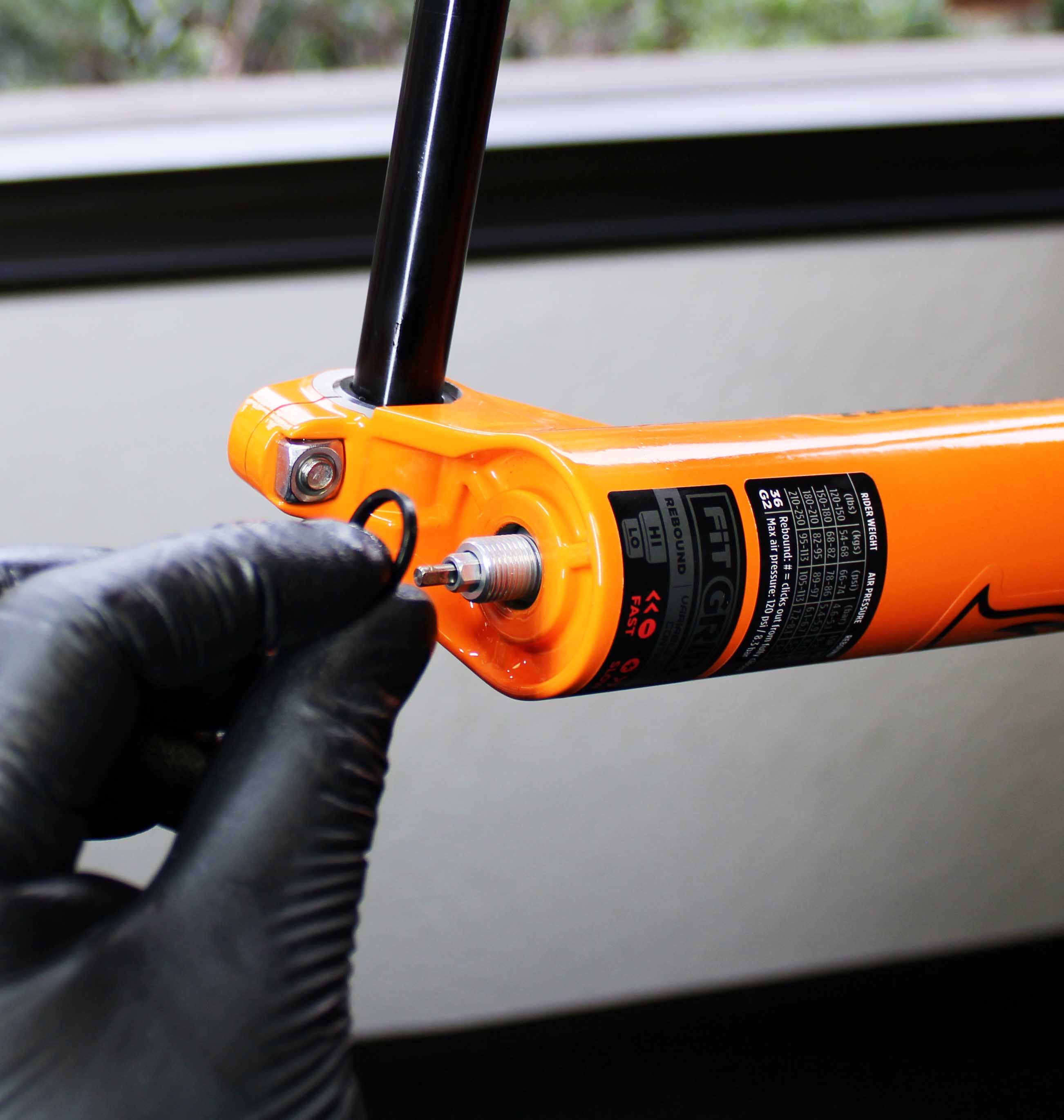
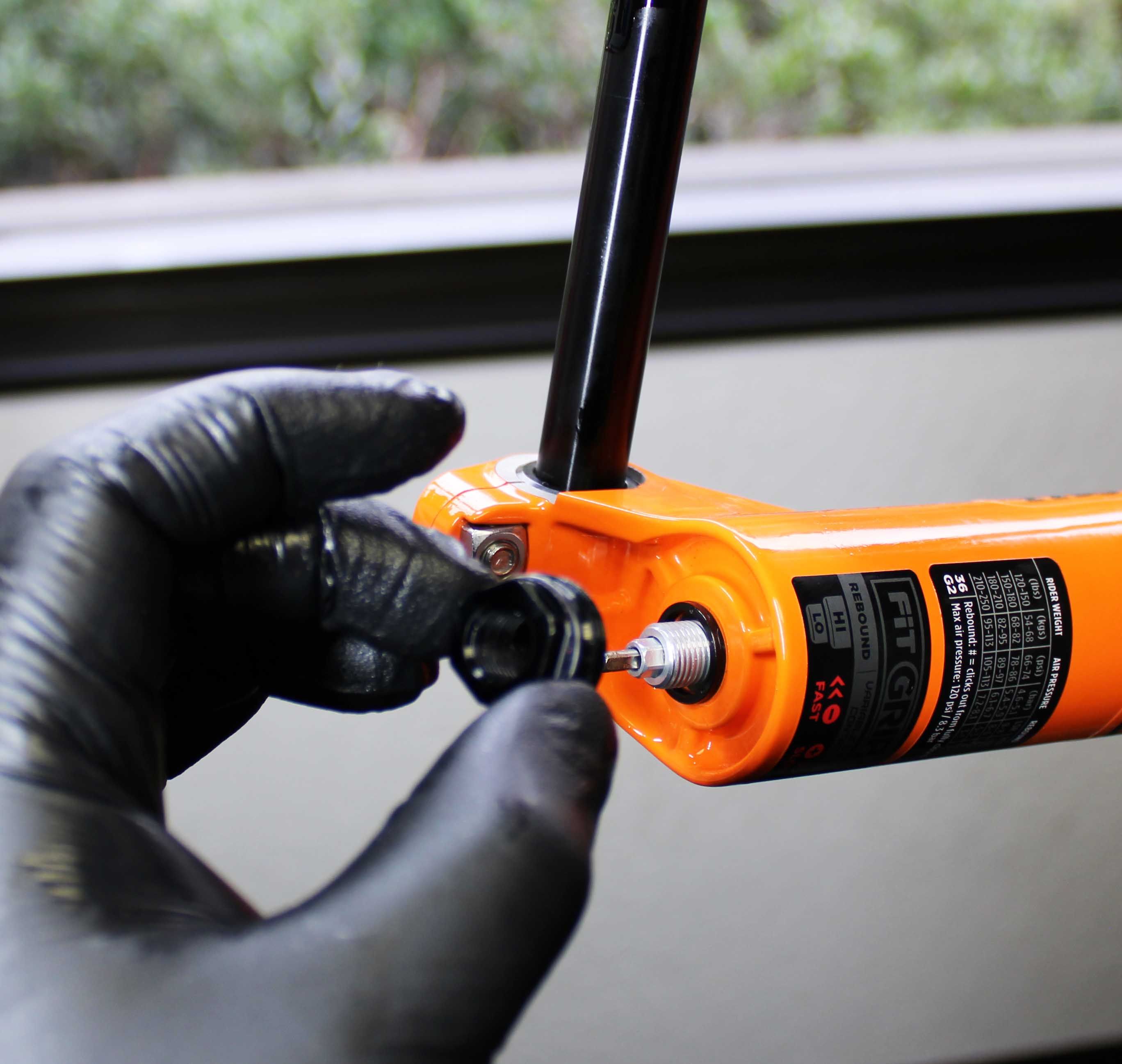
Remove the travel indicator o-ring from the air side upper tube and replace it with the new one from the kit. There is no need to lubricate this o-ring as lubrication on external parts can attract dirt and debris from the trail.


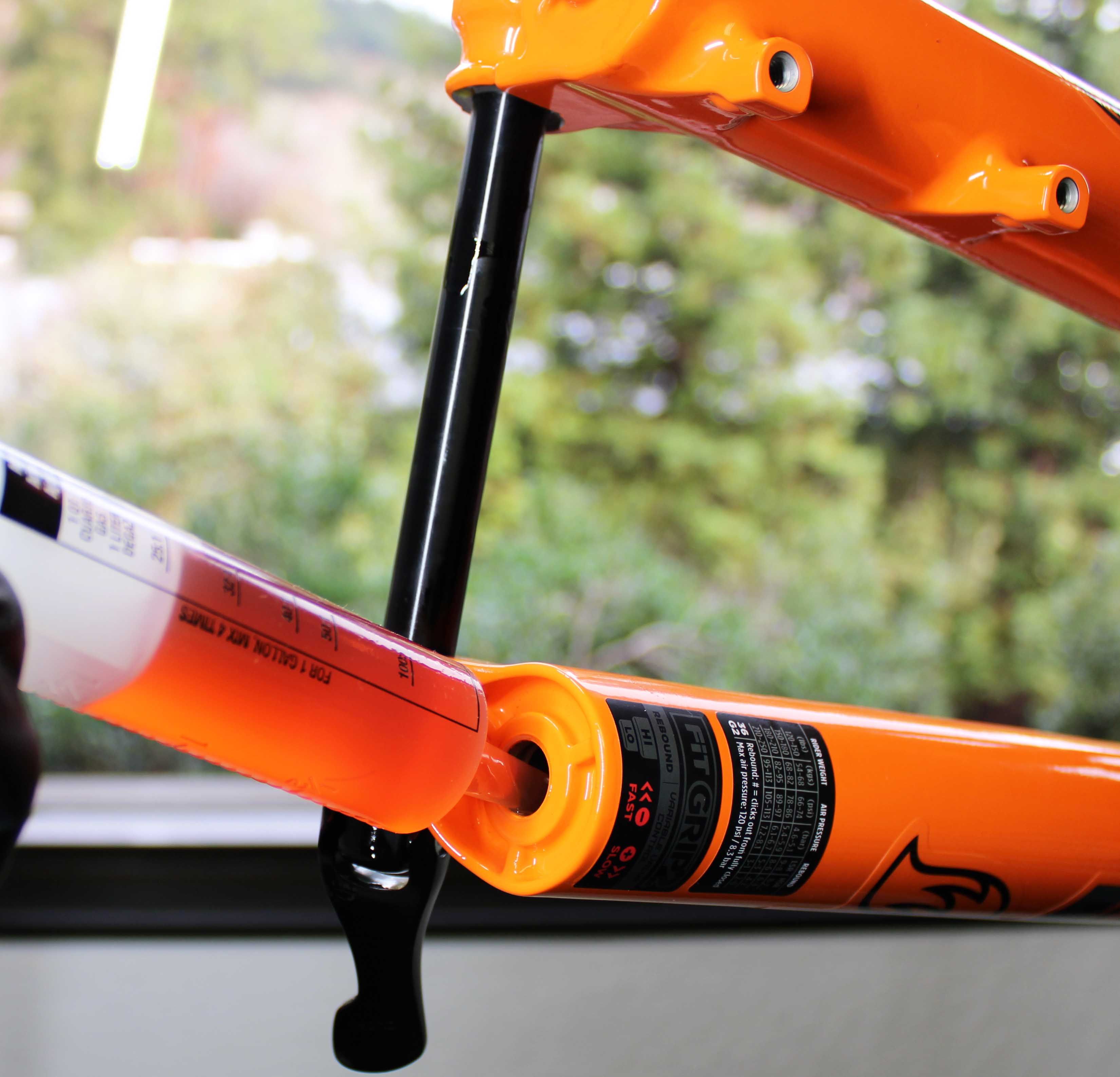
Step 13
The air spring must be fully extended before reinstalling the lower legs. Add air pressure to your desired setting using a FOX high pressure pump. See the Setting Fork Air Pressure section for more information. Reinstall the blue air cap.
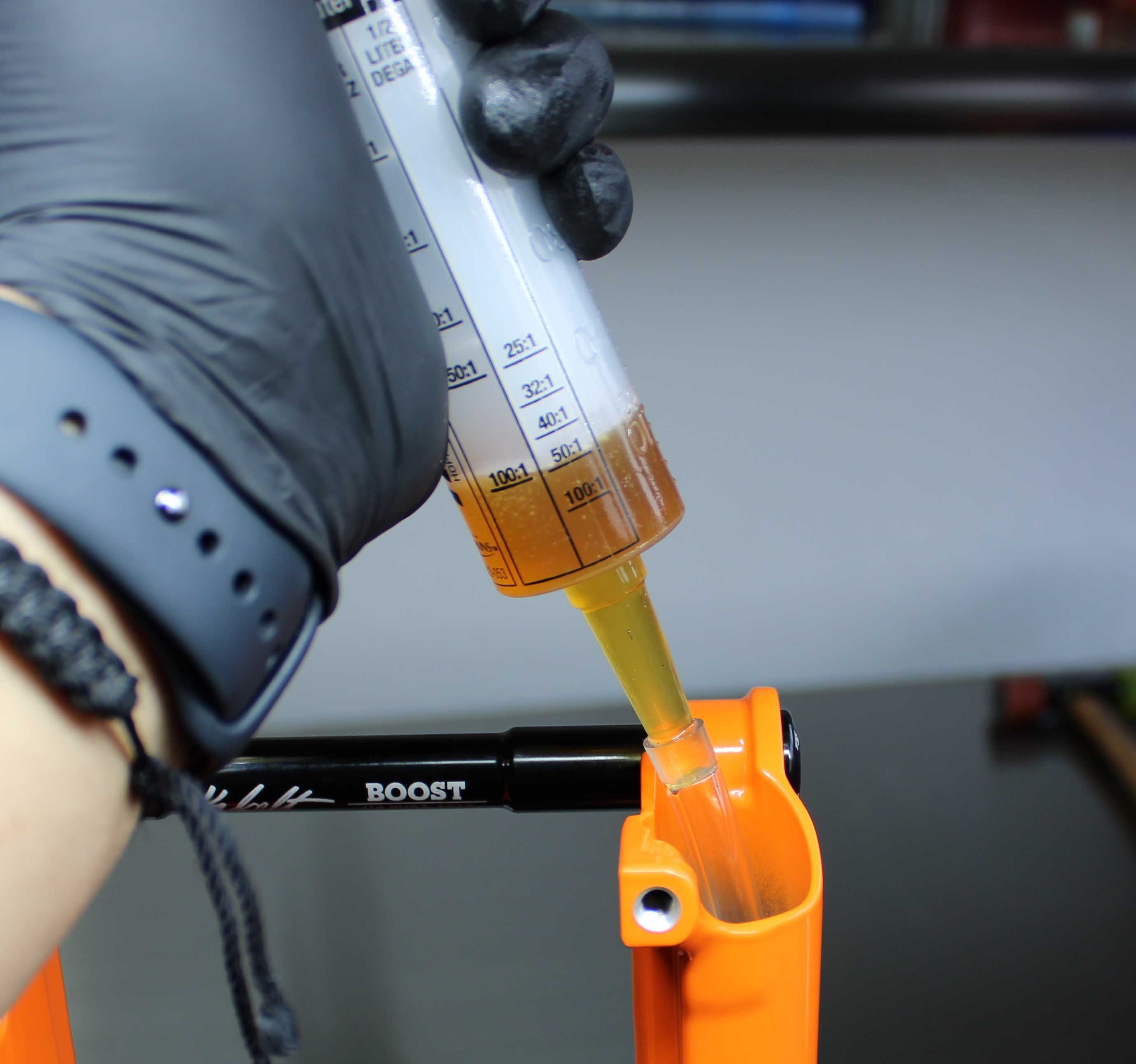
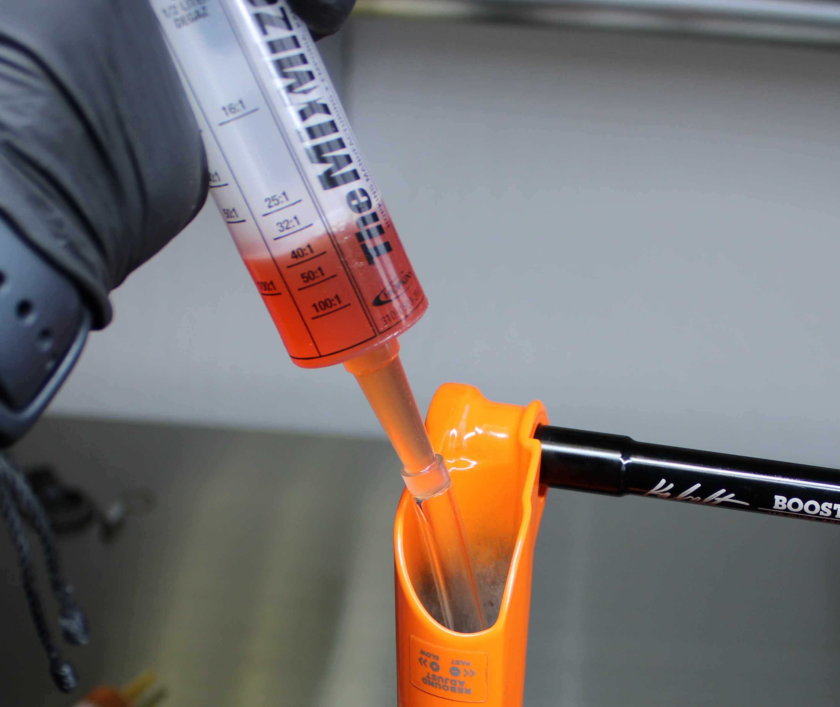
Step 14
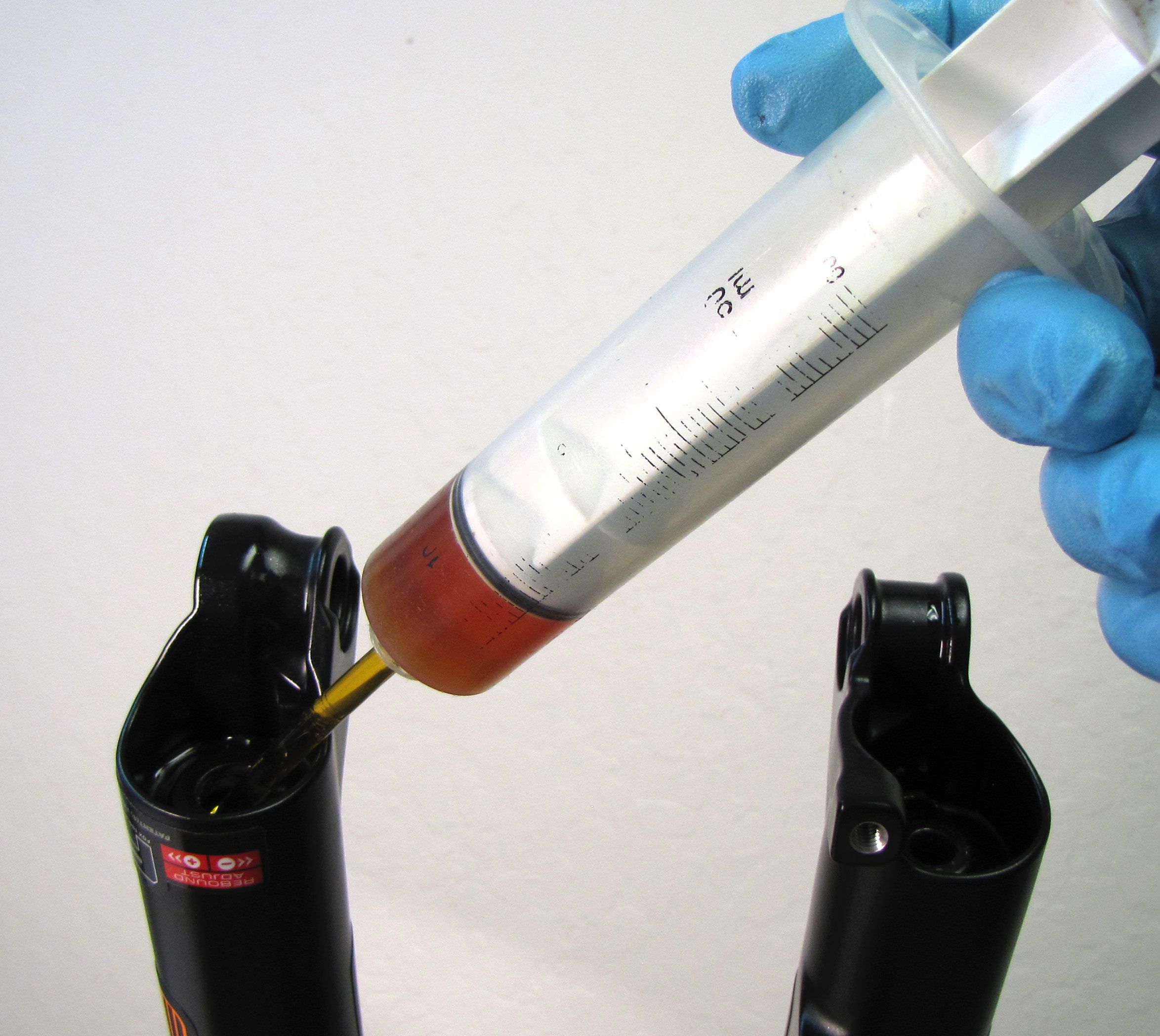
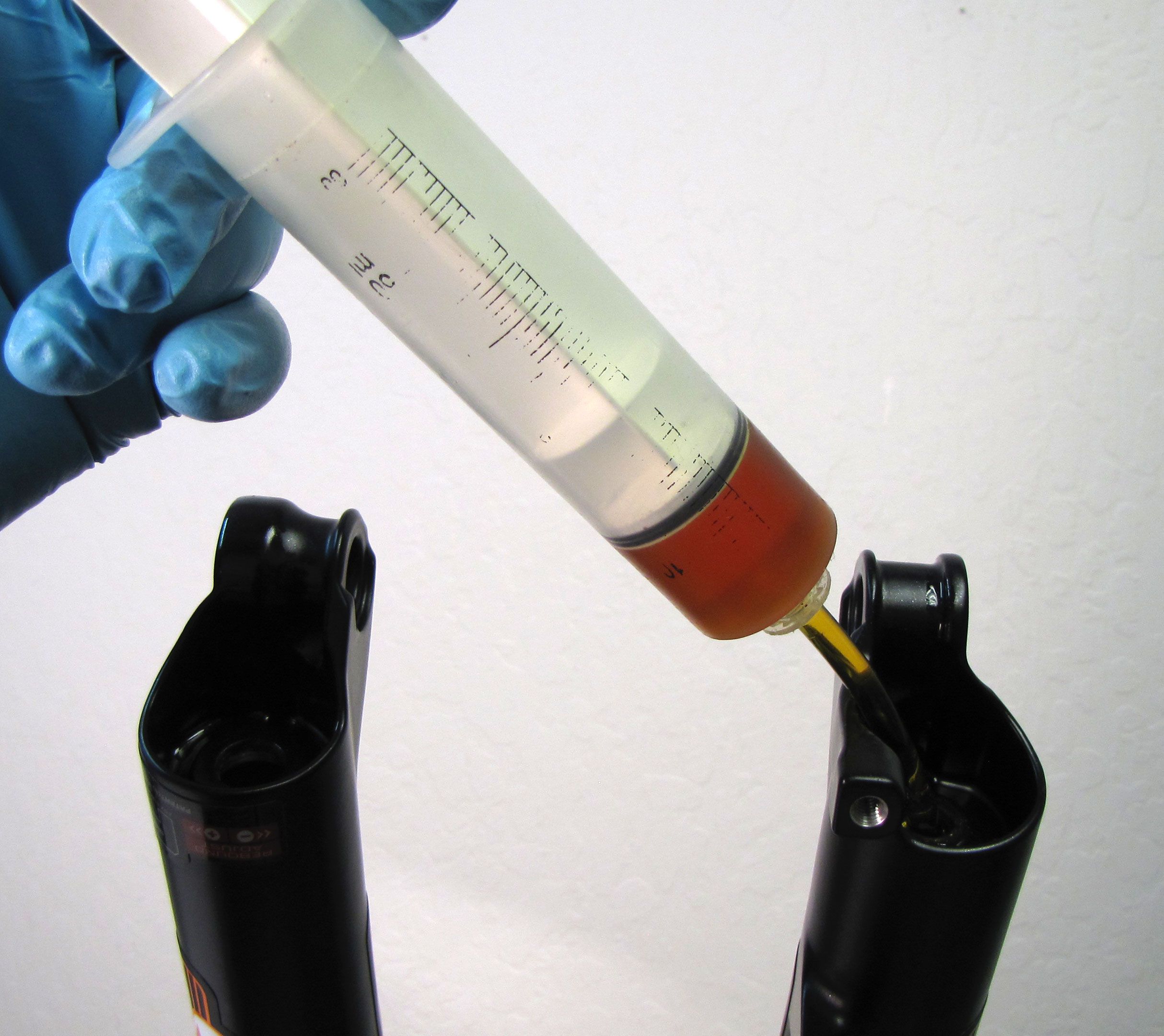
NOTE: Bath oil volumes vary by fork model.
Bath oil volumes for products can be found under "Fork- Basic Maintenance" by clicking: All Service Procedures »
Install the Lower Leg Assembly onto the upper tubes. Inject the approprate bath oil volume as listed in the bath oil volume charts.
Step 15
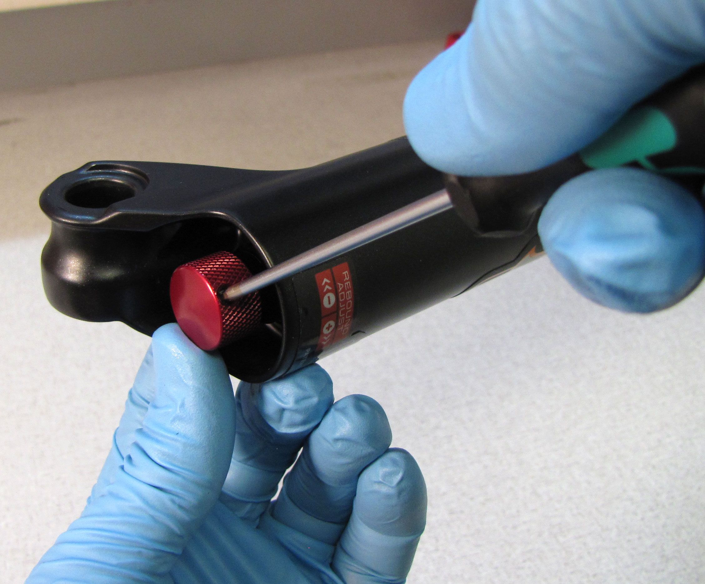
Install a new crushwasher on each side followed by the appropriate bottom nut. Torque both bottom nuts to 110in-lb (12.4 Nm) for damper side and 50in-lb(5.7Nm) for air side.


Step 16
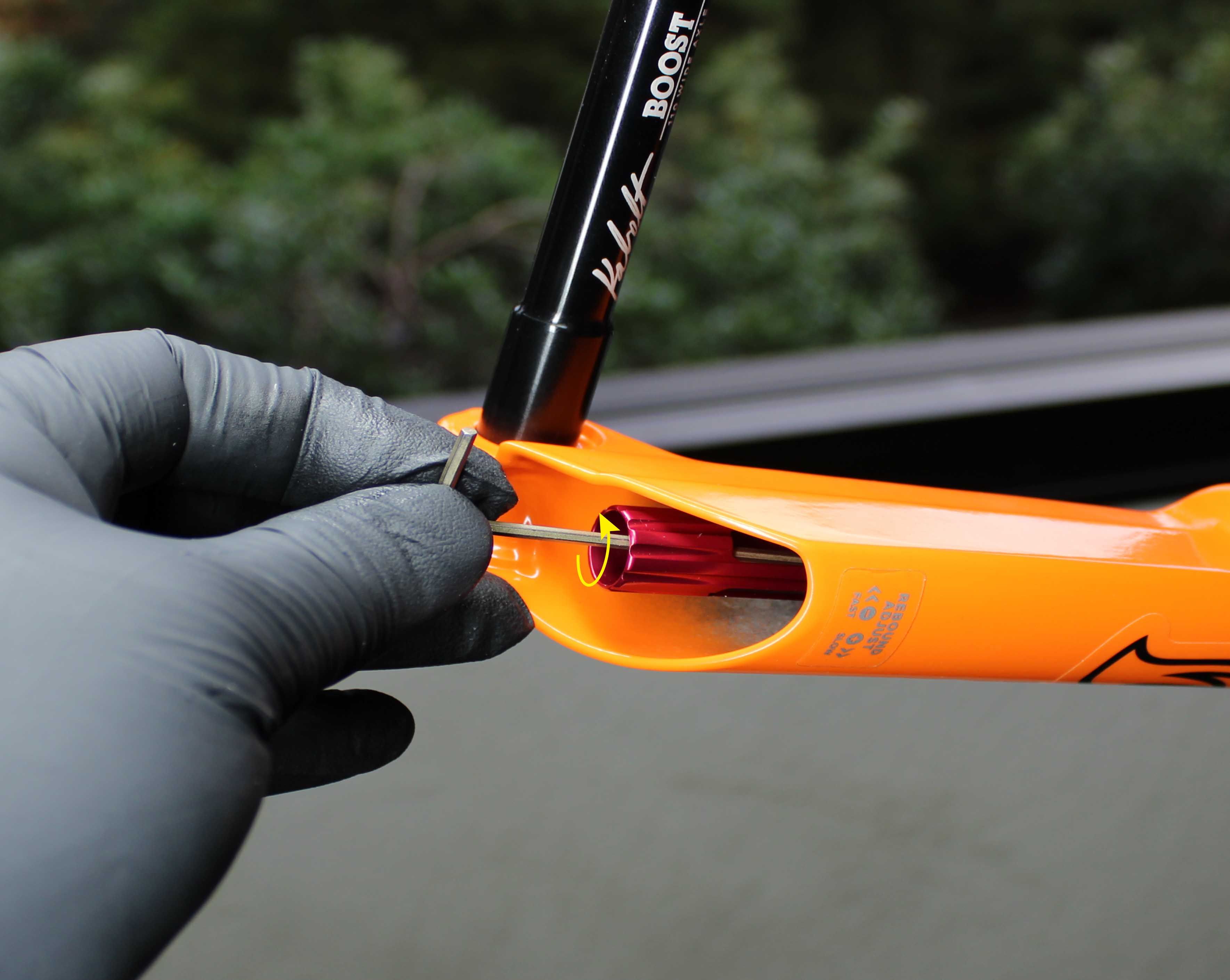
Use a 2mm hex wrench to install the red rebound knob (blue threshold adjust knob for TerraLogic forks). Make sure that the set screw lines up with the depression in the rebound adjuster shaft. Clean the exterior of your fork.