Specialized Genie Shock Tuning Kit Installation
Required Tools
- 027-00-018 Pump: Fox Digital HP w/ Bleed, Foldable, Replaceable Battery, 350 psi, Swivel Head
- Small Flat Screwdriver or Seal Pick .
WARNING: FOX products should be serviced by a trained bicycle service technician, in accordance with FOX specifications. If you have any doubt whether or not you can properly service your FOX product, then DO NOT attempt it. Improperly serviced products can fail, causing the rider to lose control resulting in SERIOUS INJURY OR DEATH.
WARNING: FOX suspension products contain pressurized nitrogen, air, oil, or all 3. Suspension misuse can cause property damage, SERIOUS INJURY OR DEATH. DO NOT puncture, incinerate or crush any portion of a FOX suspension product. DO NOT attempt to disassemble any portion of a FOX suspension product, unless expressly instructed to do so by the applicable FOX technical documentation, and then ONLY while strictly adhering to all FOX instructions and warnings in that instance.
WARNING: Modification, improper service, or use of aftermarket replacement parts with FOX forks and shocks may cause the product to malfunction, resulting in SERIOUS INJURY OR DEATH. DO NOT modify any part of a fork or shock, including the fork brace (lower leg cross brace), crown, steerer, upper and lower leg tubes, or internal parts, except as instructed herein. Any unauthorized modification may void the warranty, and may cause failure or the fork or shock, resulting in SERIOUS INJURY OR DEATH.
WARNING: Never attempt to modify air volume or travel spacers, as this can damage your shock causing a loss of control of the bicycle leading to SERIOUS INJURY or DEATH.
The Specialized Genie Shock Tuning Kit from FOX allows you to change air volume spacers in the main air chamber and air sleeve in addition to changing travel. Follow the instructions below to add or remove air volume and travel spacers as needed to achieve desired performance.
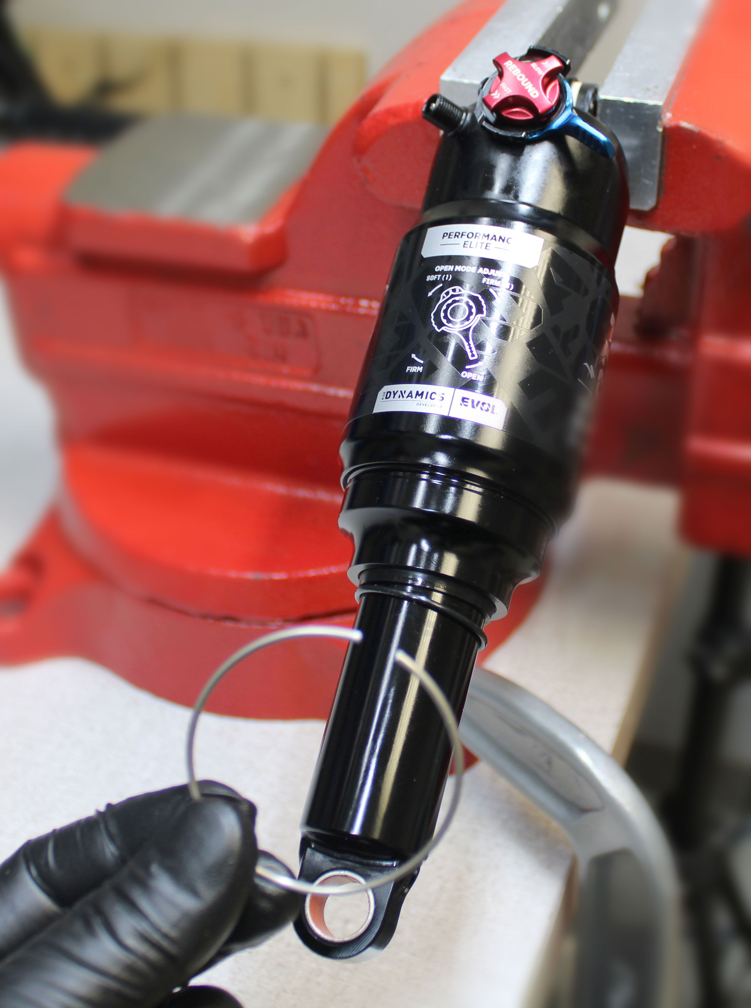
Step 1
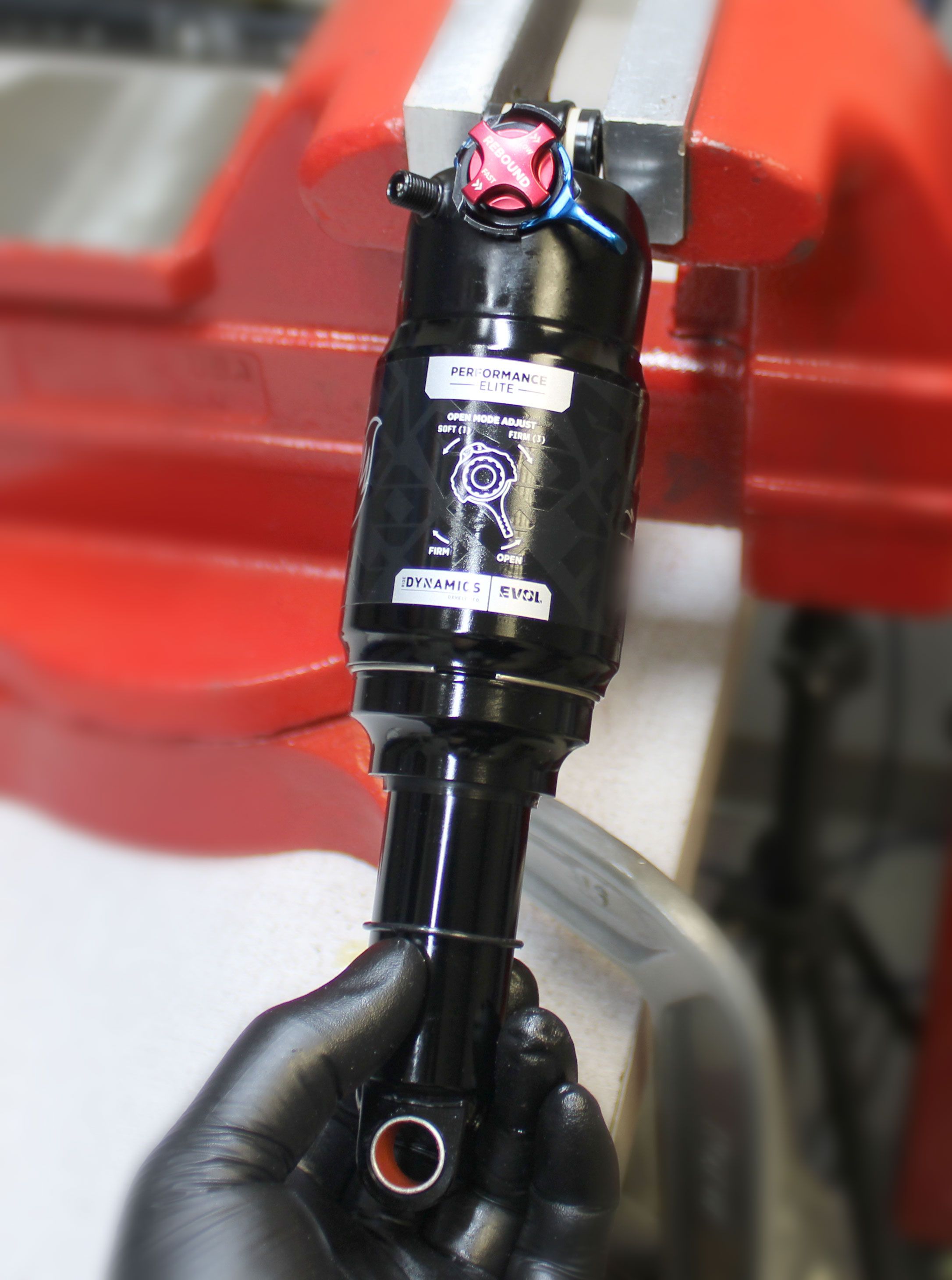
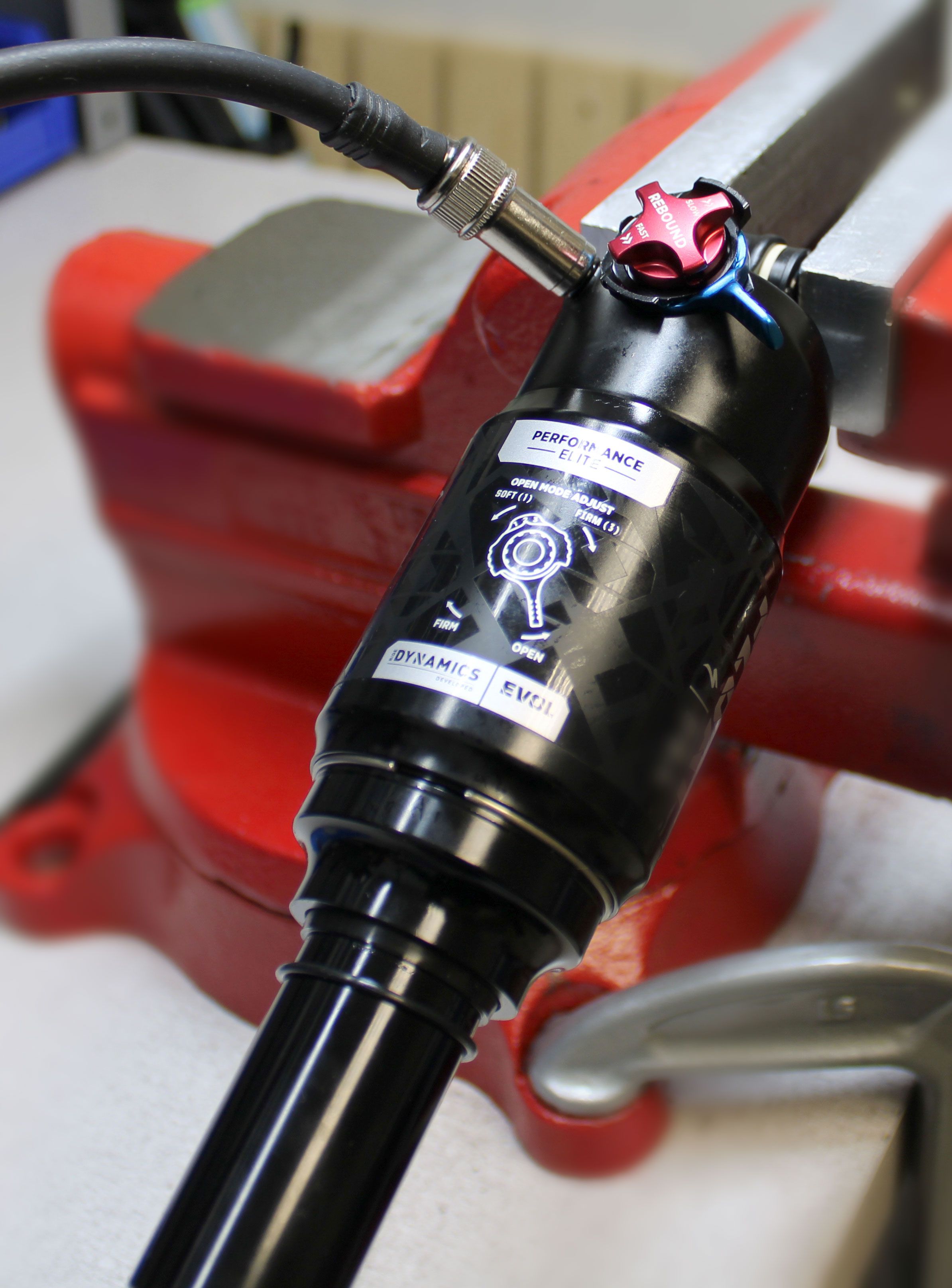
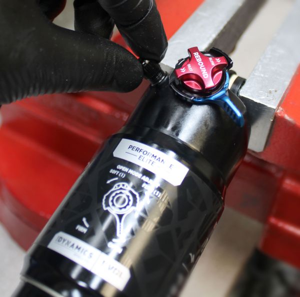
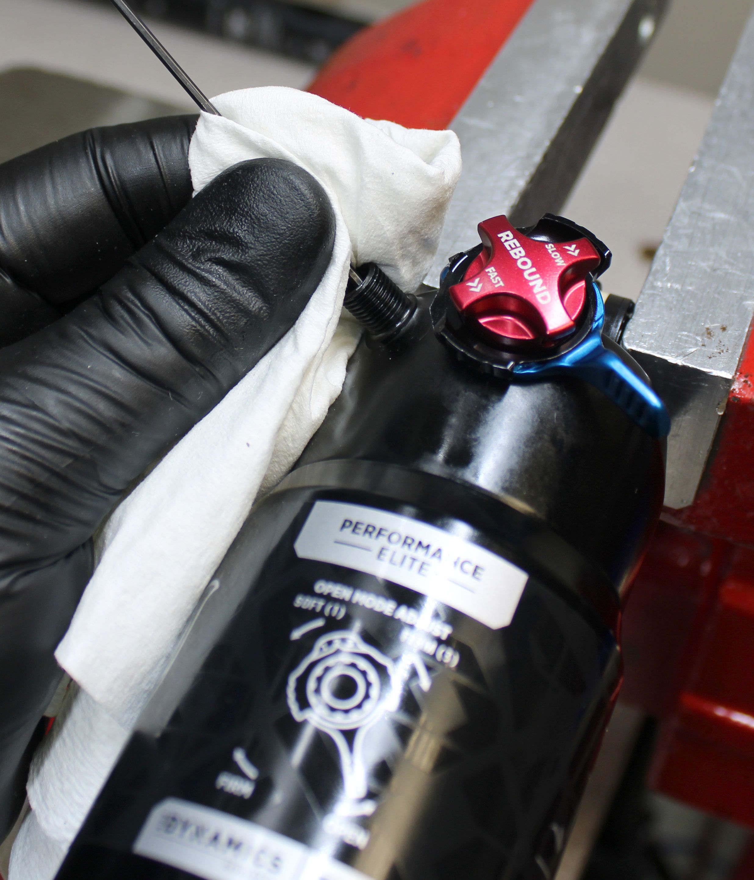
Remove the black air cap and thread on your FOX shock pump. Slowly release all air from the main air chamber with your pump, then remove the pump. Verify that all air has been released by depressing the Schrader valve.


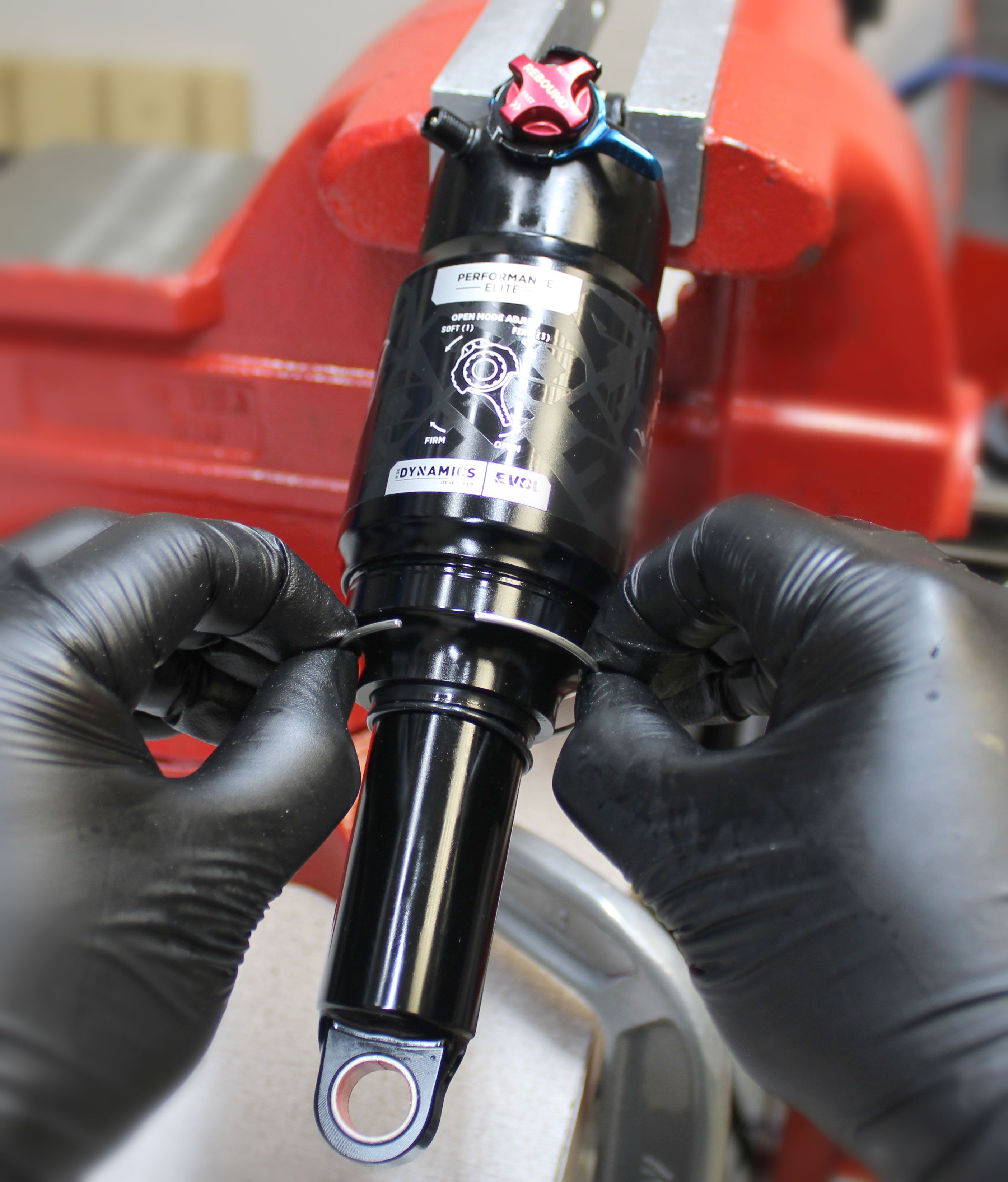
Step 2
XV Sleeve Volume Spacers
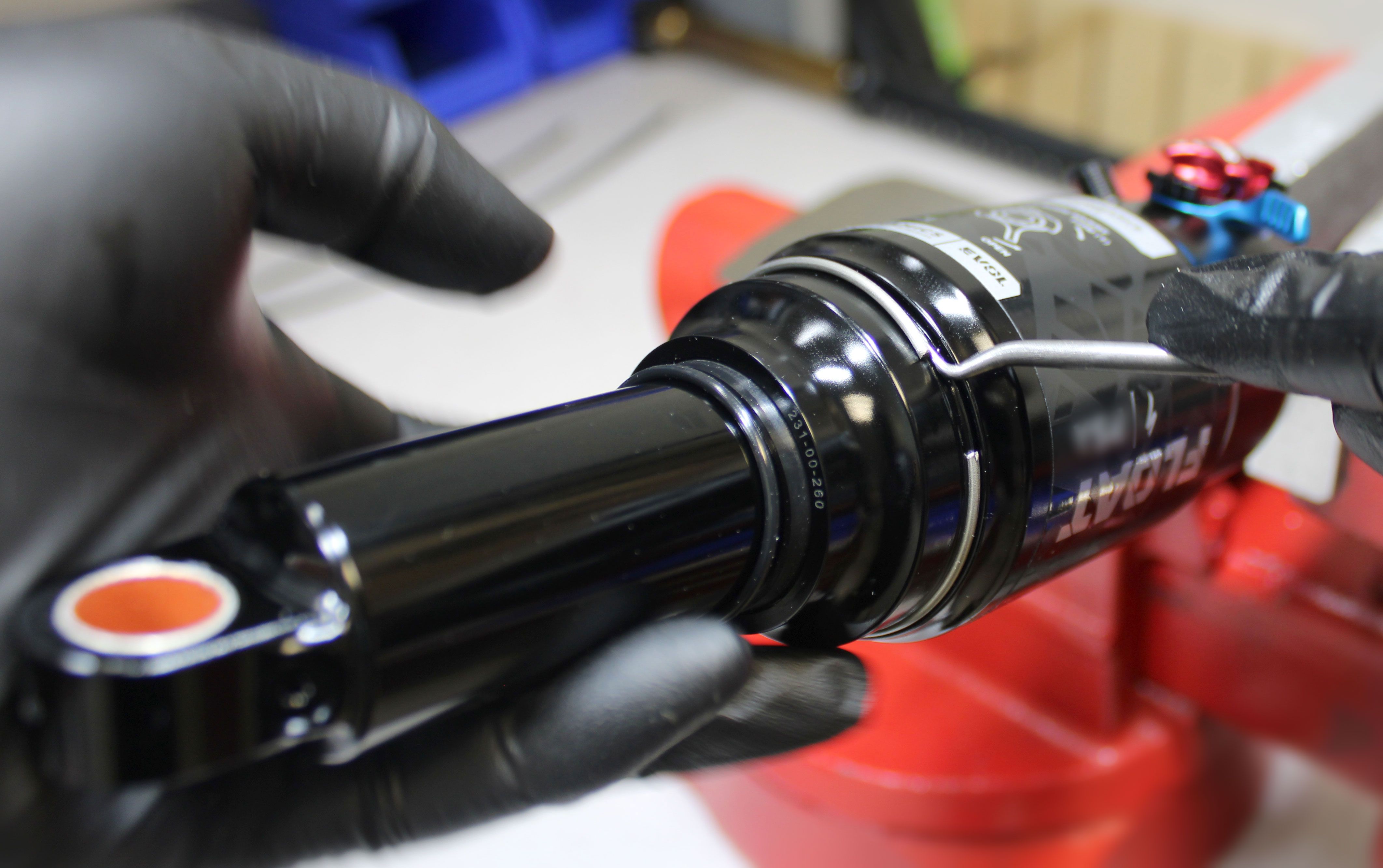
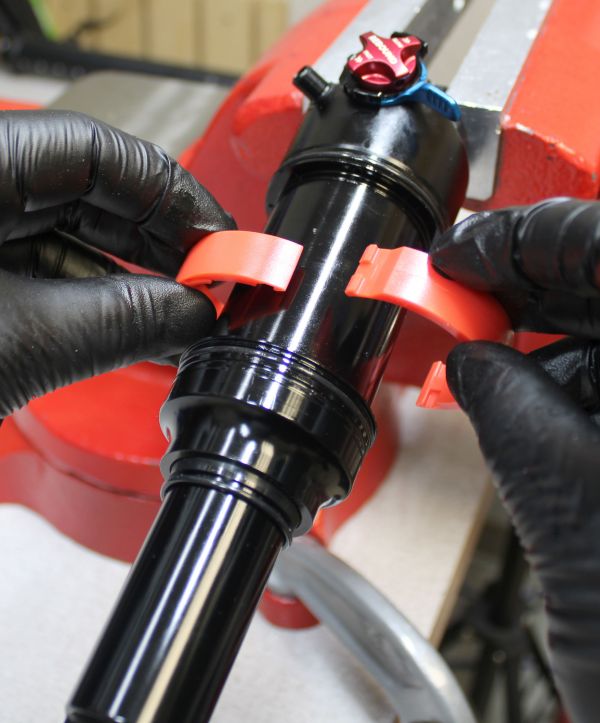
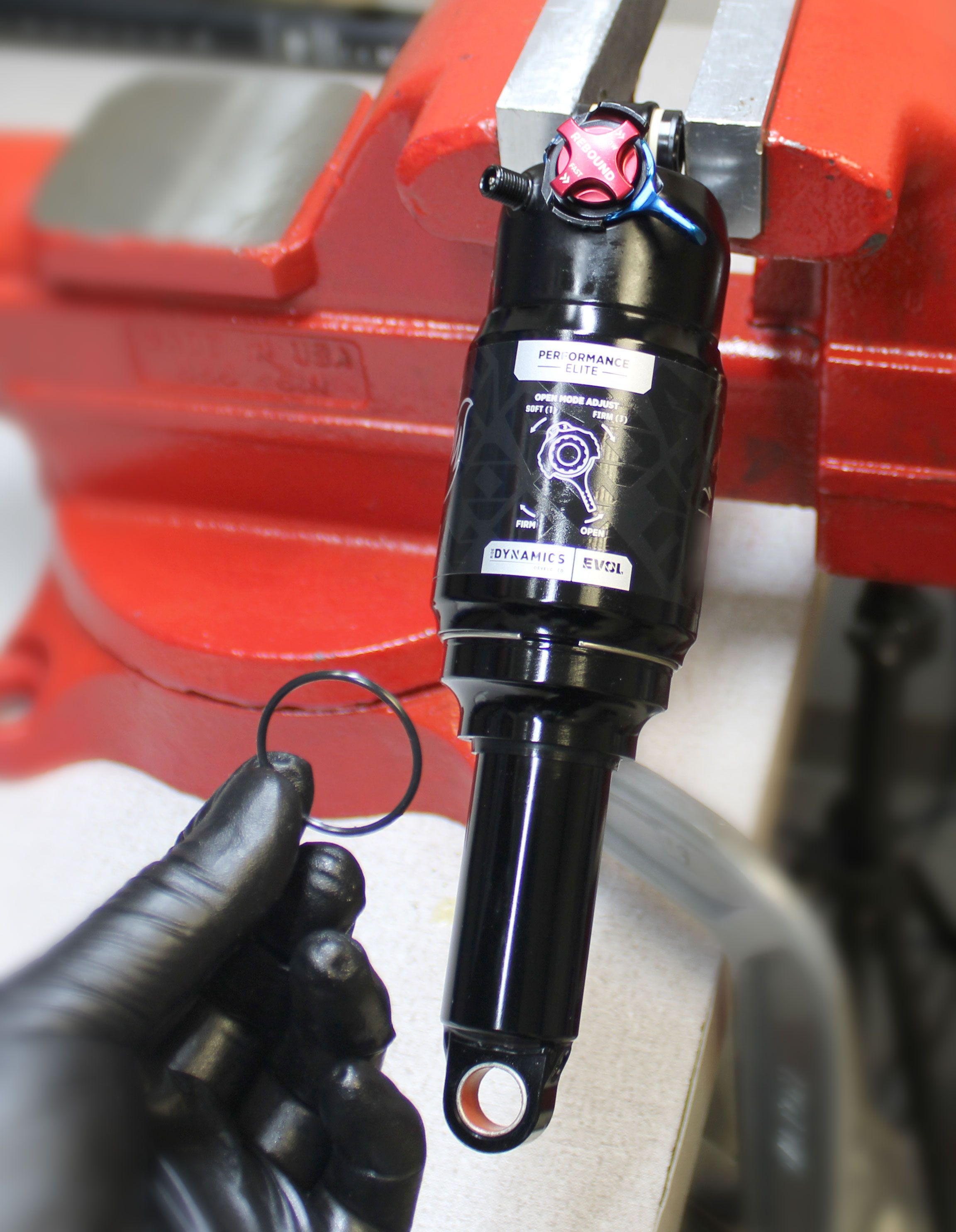
Use a small flat driver or seal pick to remove the wire retaining ring from the Extra Volume (XV) sleeve. Remove the XV sleeve by pulling it down away from the main air sleeve.
DO NOT let the ends of the wire retaining ring contact the shock during removal as it can cause damage to the surface finish.
Step 3
XV Sleeve Volume Spacers
Add volume spacers to the XV sleeve by clipping them together in pairs. You can remove spacers by unclipping them from each other.
DO NOT exceed a maximum of 4 pairs of XV sleeve air volume spacers.

Step 4
XV Sleeve Volume Spacers
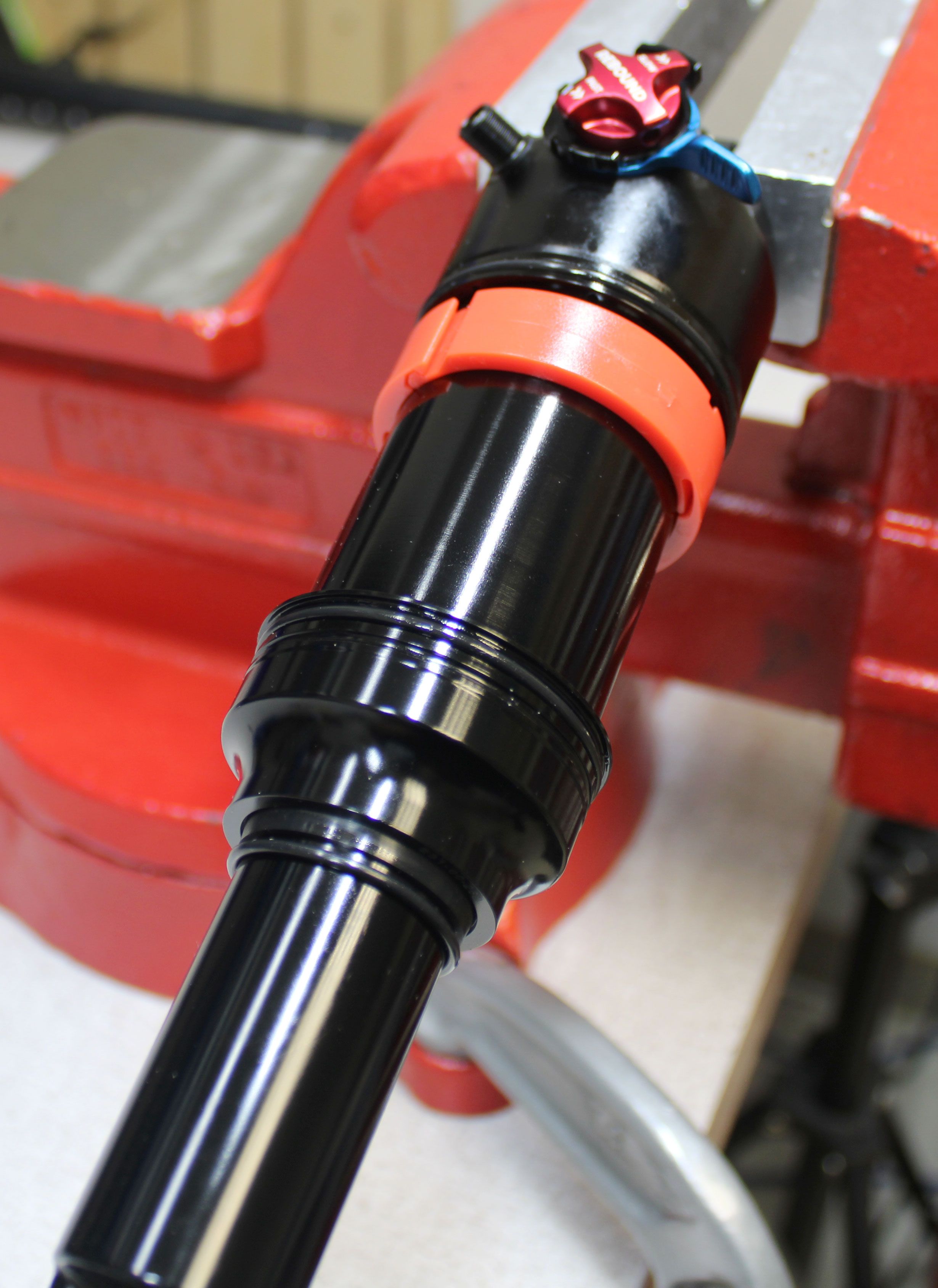
Reinstall the XV sleeve by sliding it up, making sure to fully seat the XV sleeve on the main air sleeve. Reinstall the wire retaining ring making sure to fully seat the ring in the groove.
DO NOT let the ends of the wire retaining ring contact the shock during installation as it can cause damage to the surface finish.


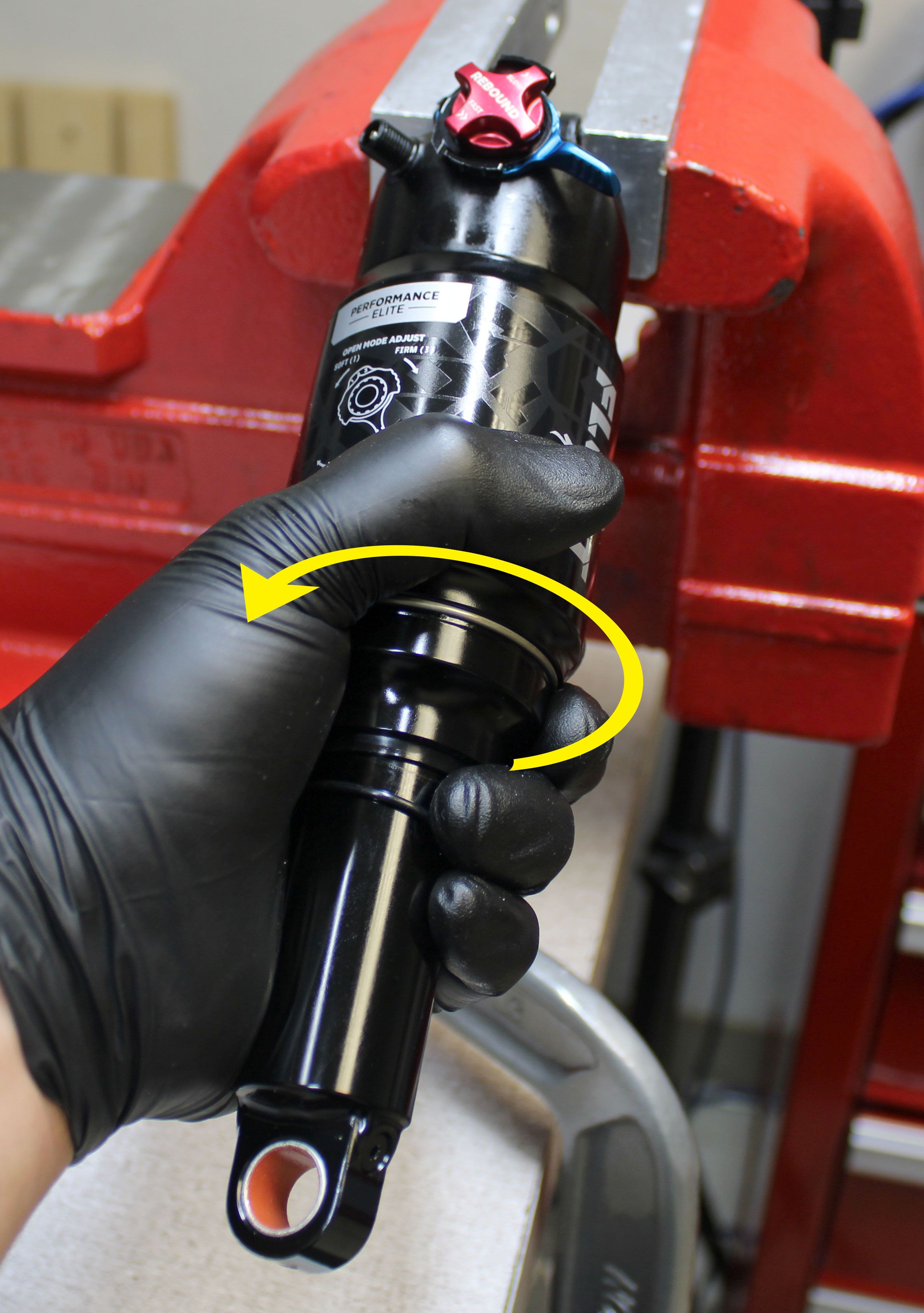
Step 5
Main Air Chamber Volume Spacers
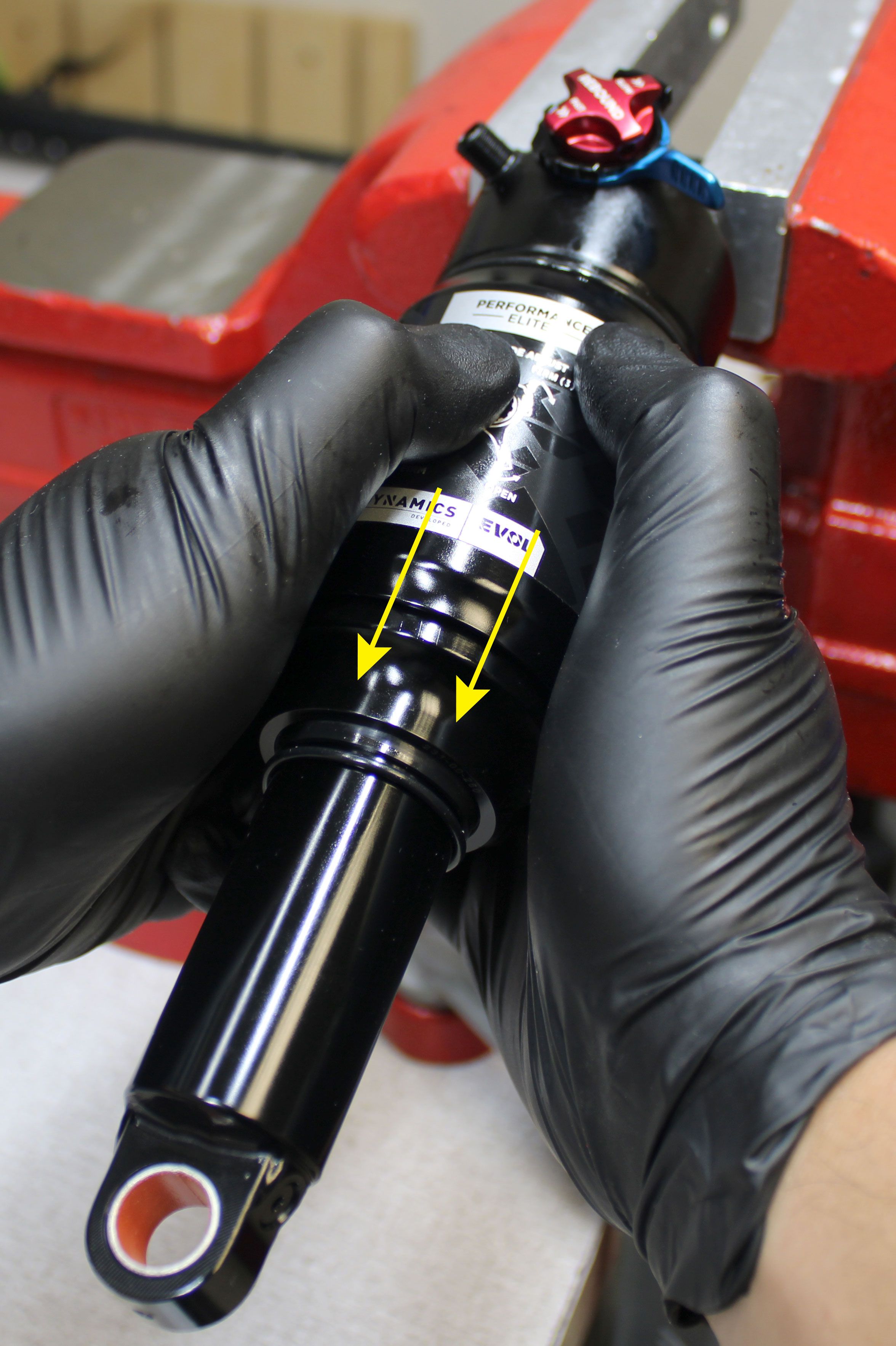
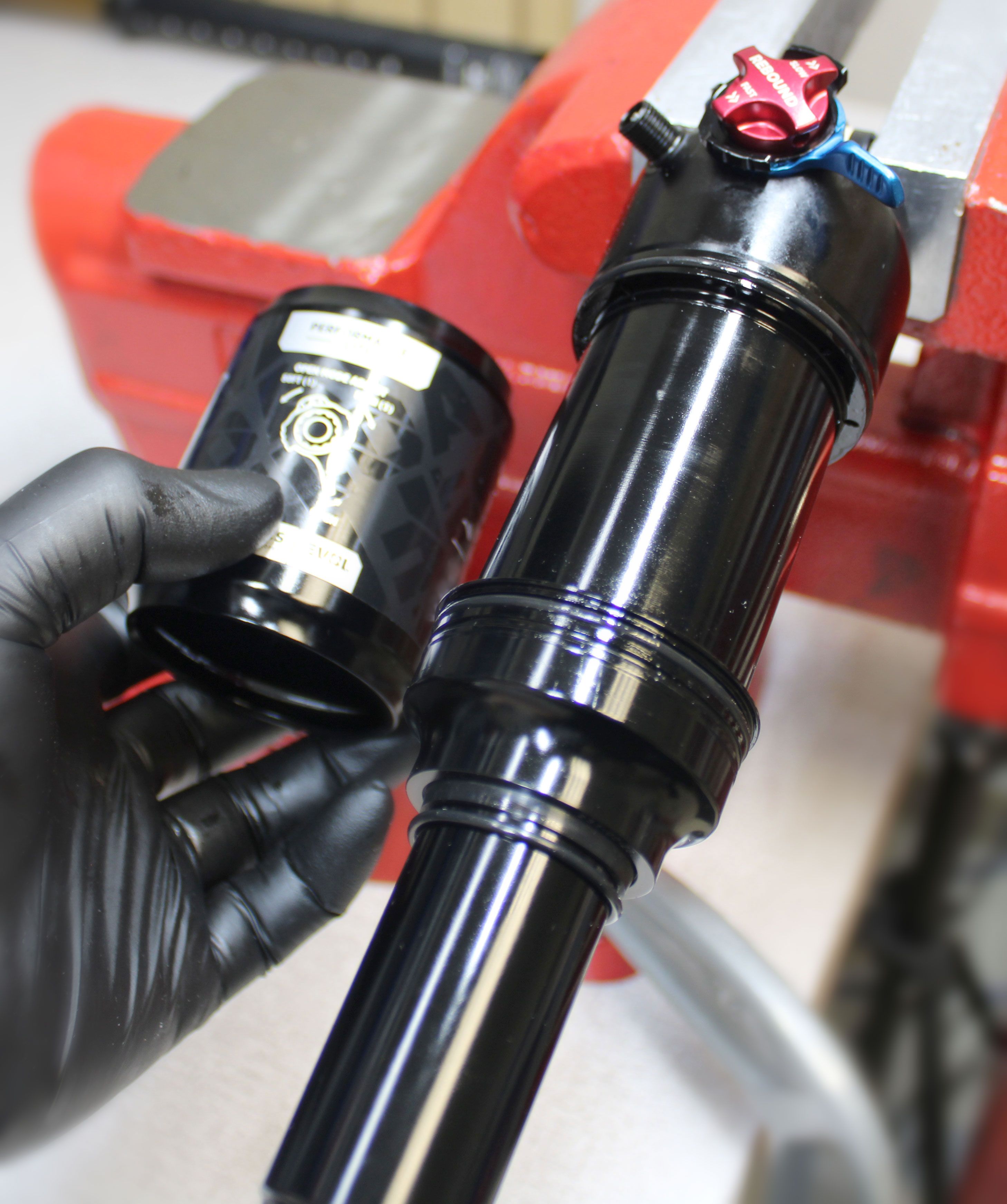
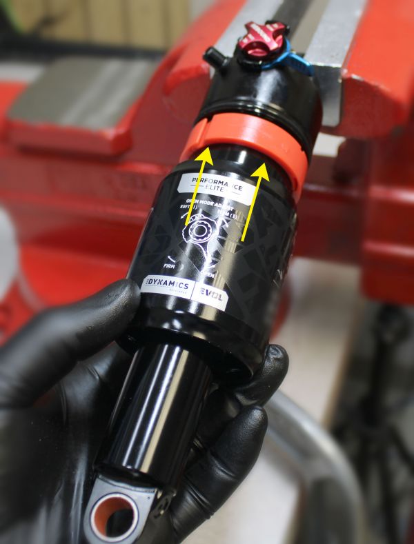
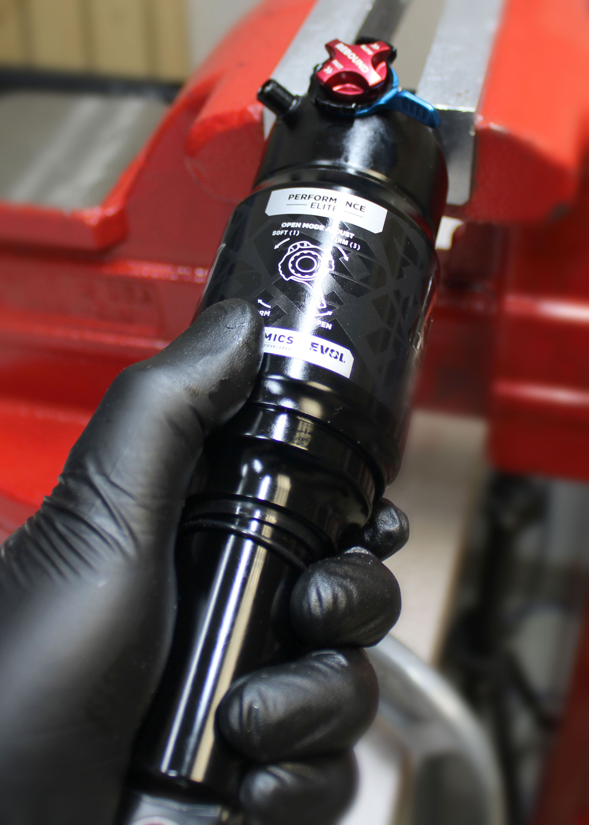
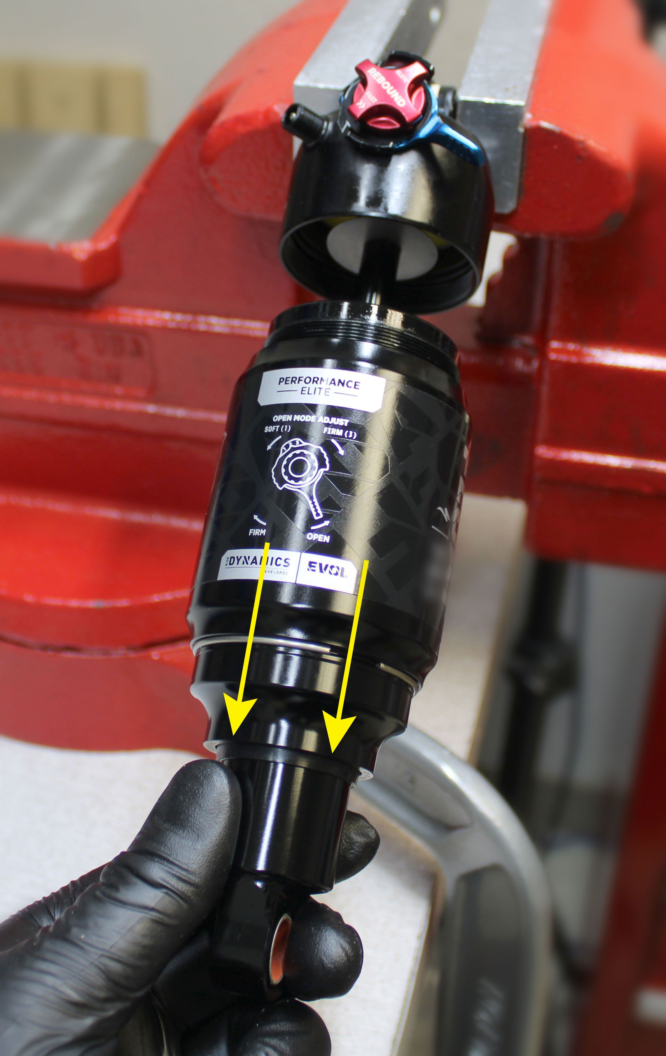
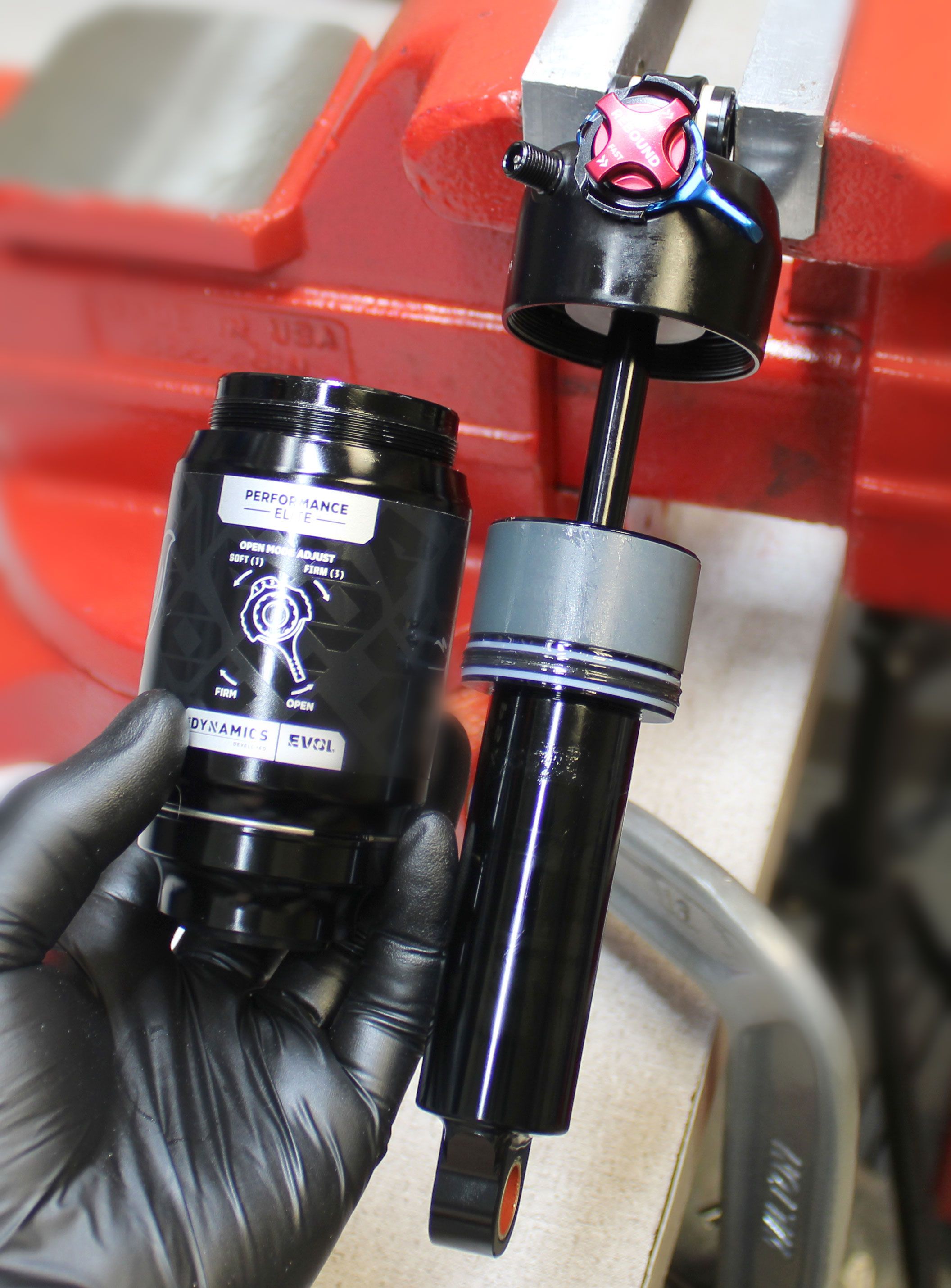
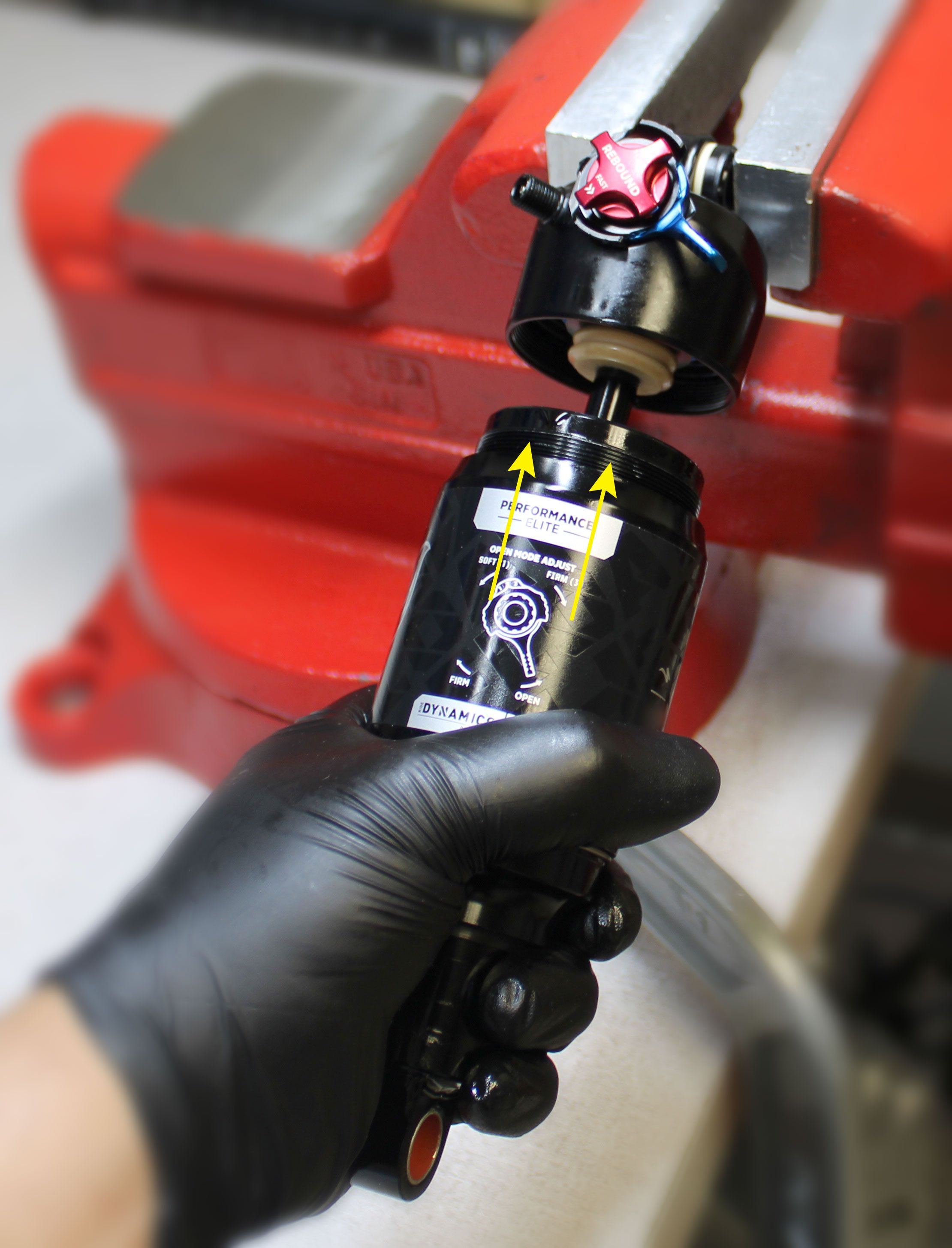
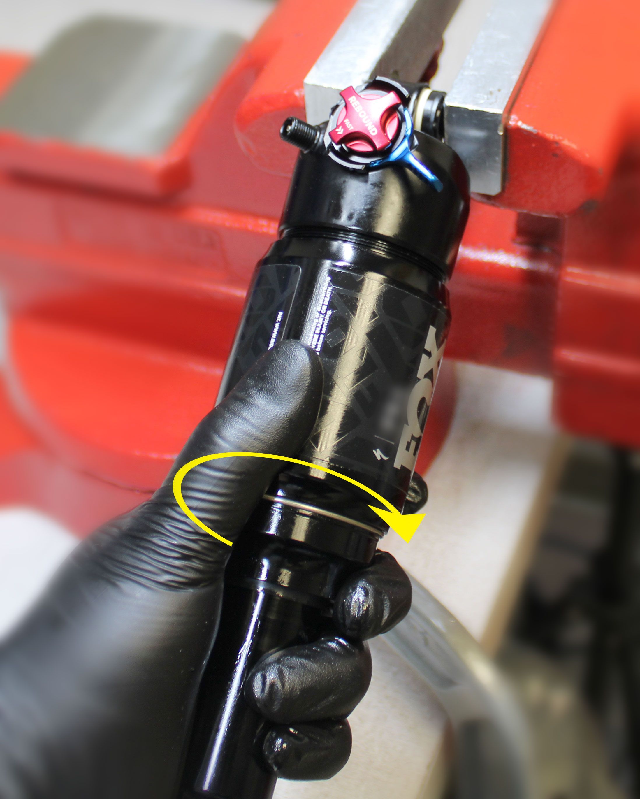
Unthread the air sleeve counter-clockwise by holding the exposed portion of the main air sleeve beneath the XV sleeve. Slide the air sleeve down to access the main air chamber volume spacer.
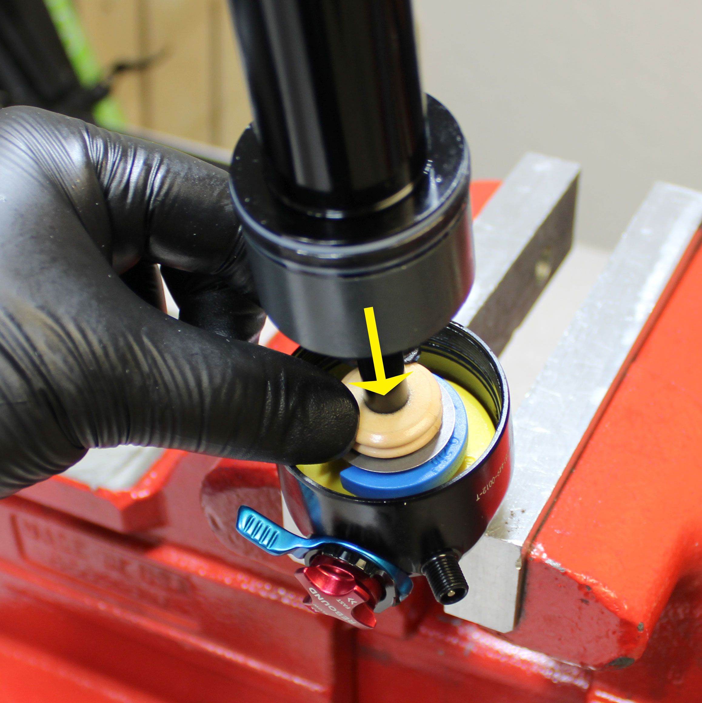
Step 6
Main Air Chamber Volume Spacers
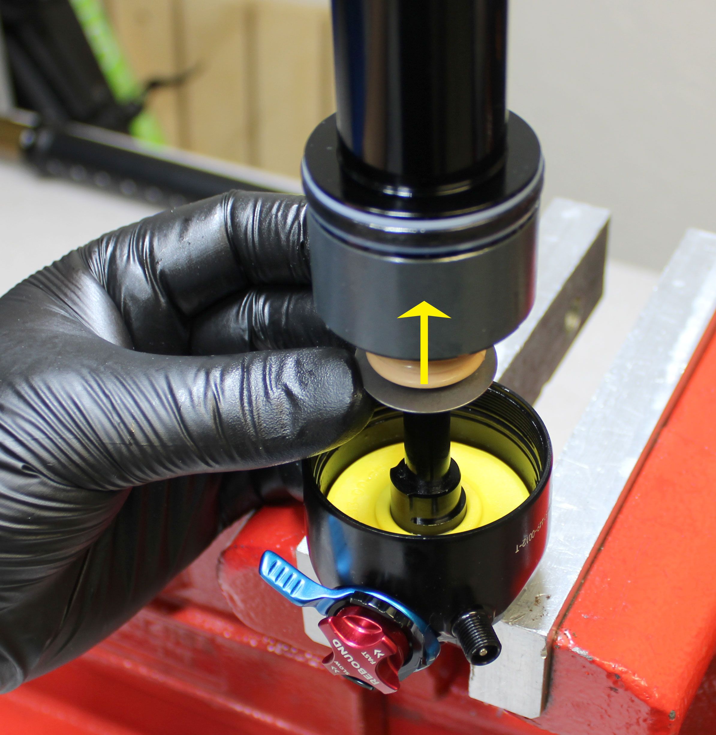
Slide the bottom out bumper and bottom out plate down the shaft to access the air volume spacer.
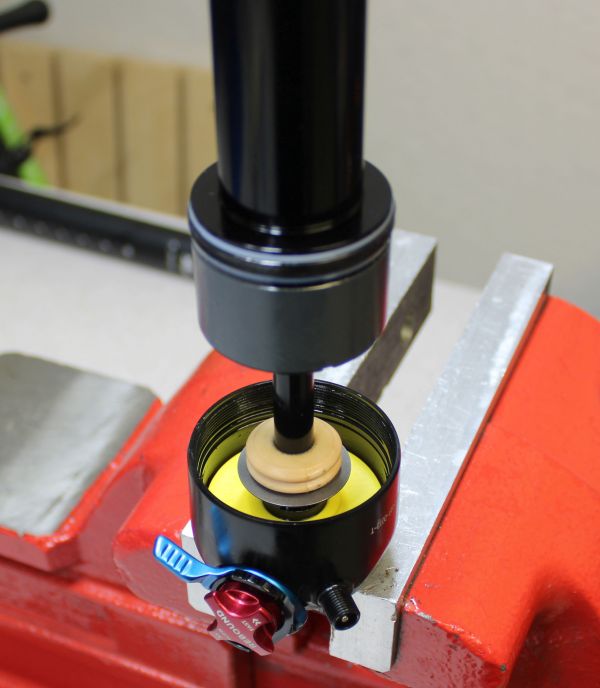
NOTE: The yellow air volume spacer should be considered permanent. DO NOT attempt to remove the yellow air volume spacer.

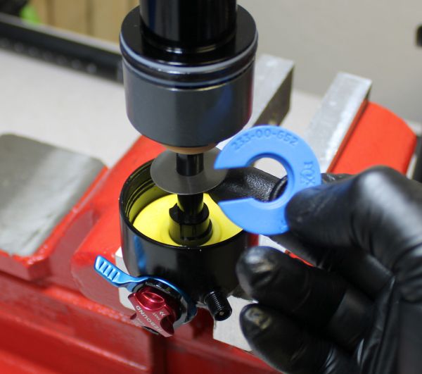
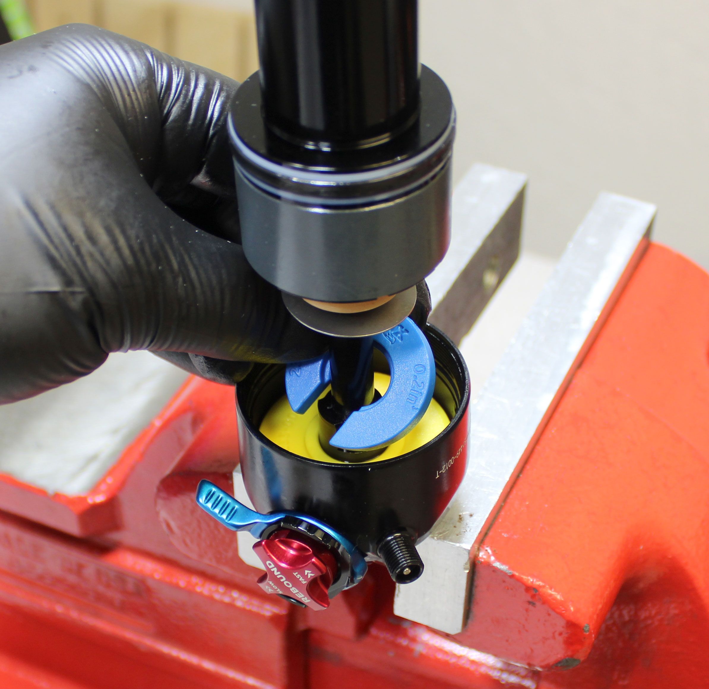
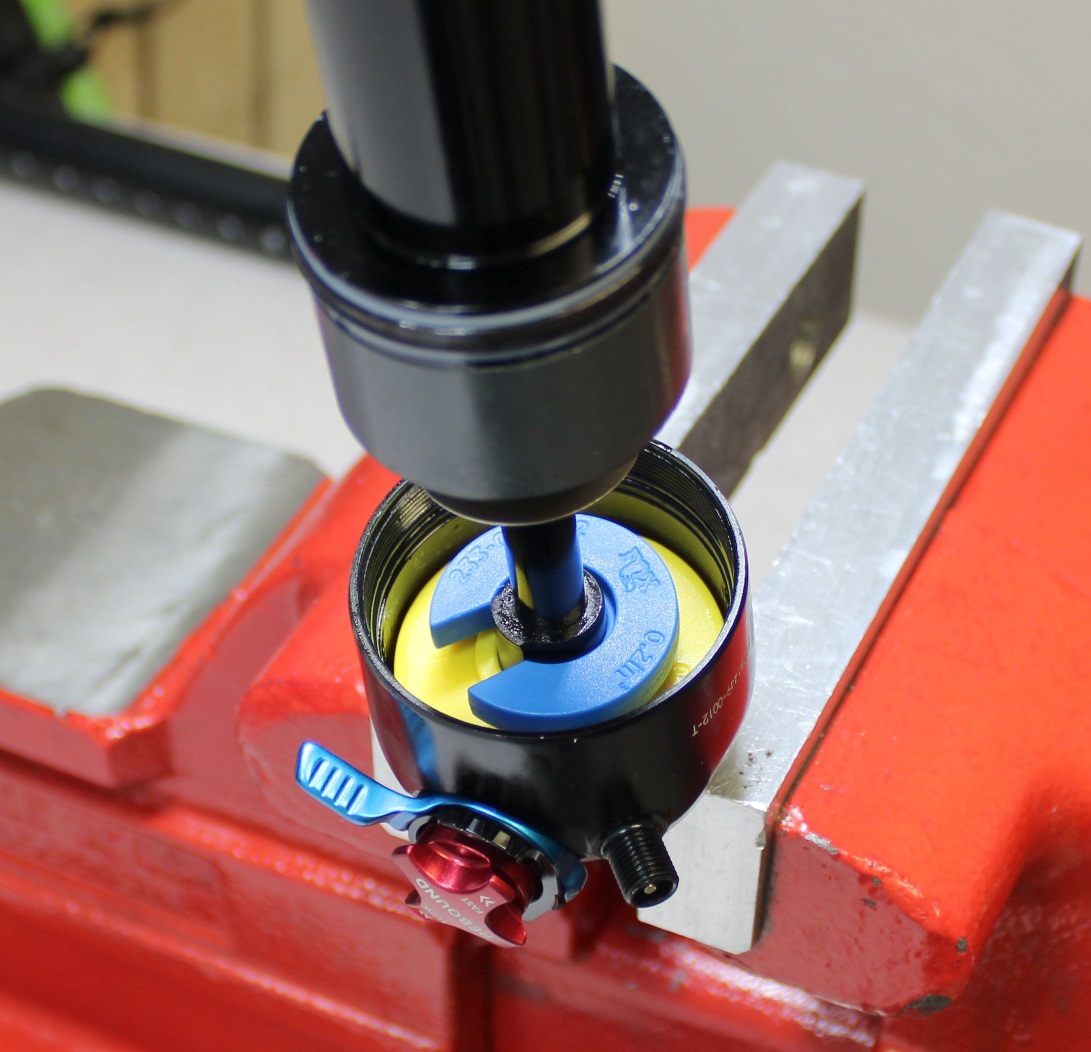
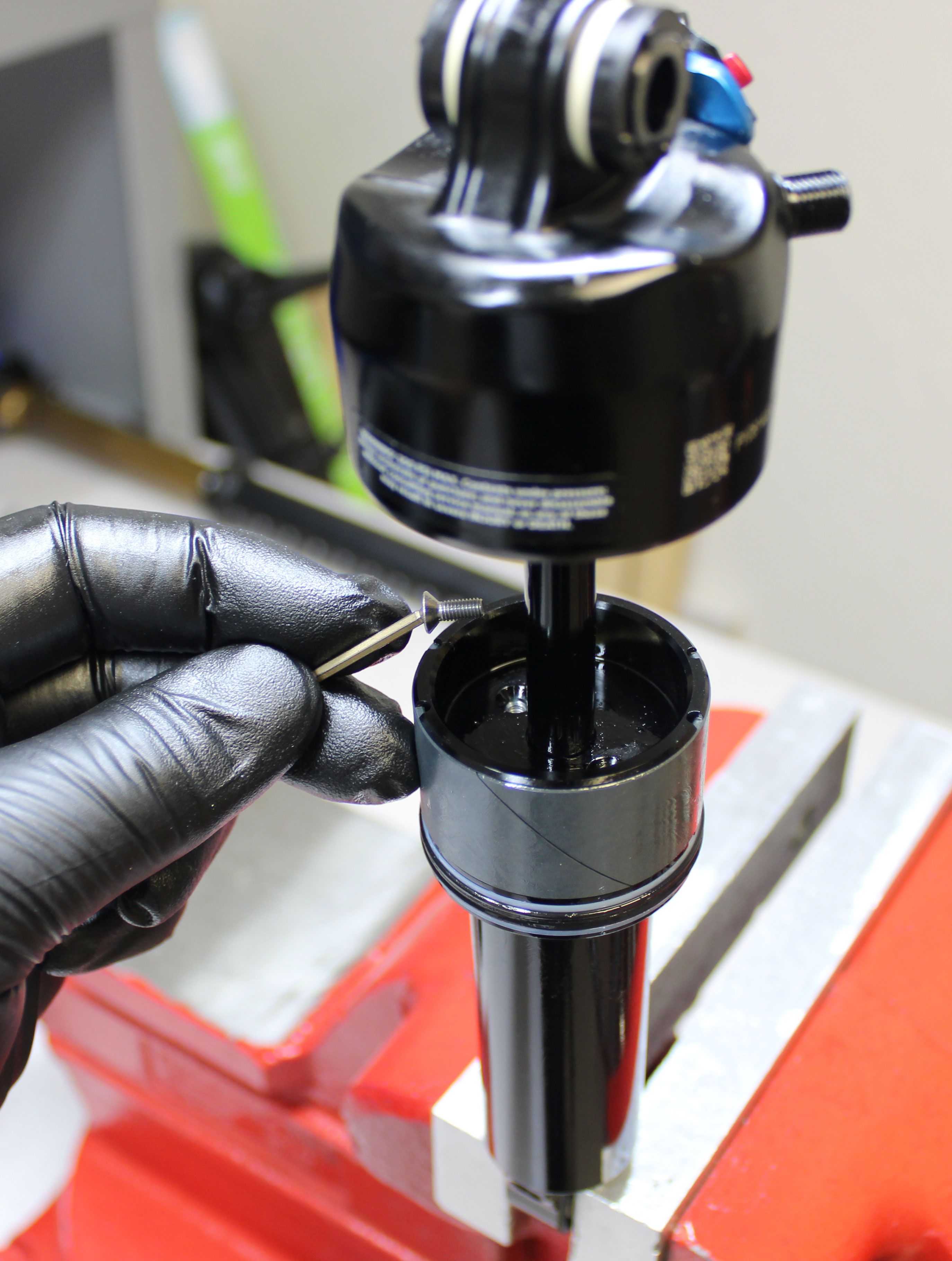
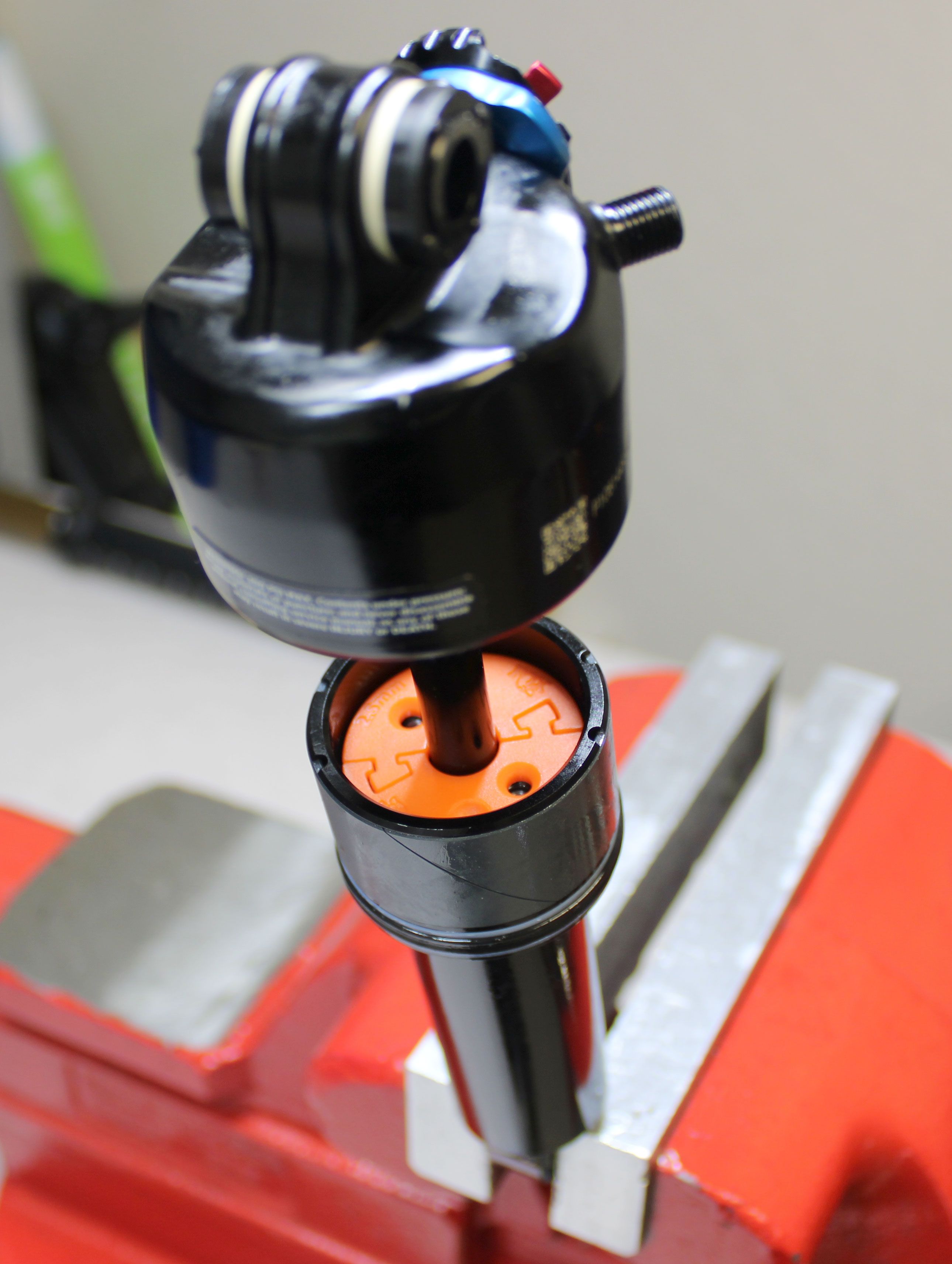
Step 7
Main Air Chamber Volume Spacers
Install the new air volume spacer from the kit into the eyelet as shown. Make sure that the FOX logo is visible when installed in the eyelet and that the air volume spacer is fully seated. Slide the bottom out plate and bottom out bumper up the shaft against the new air volume spacer.

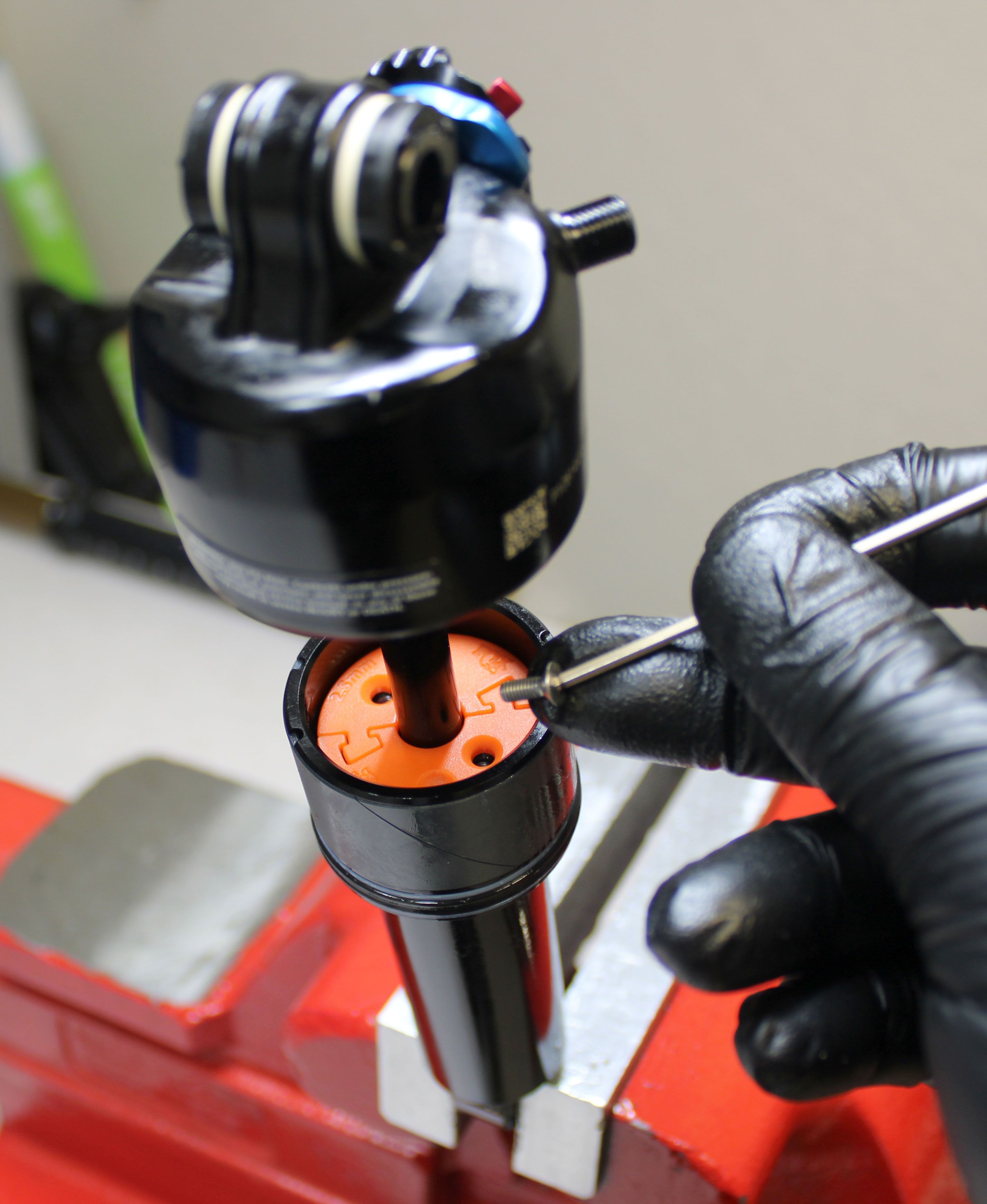
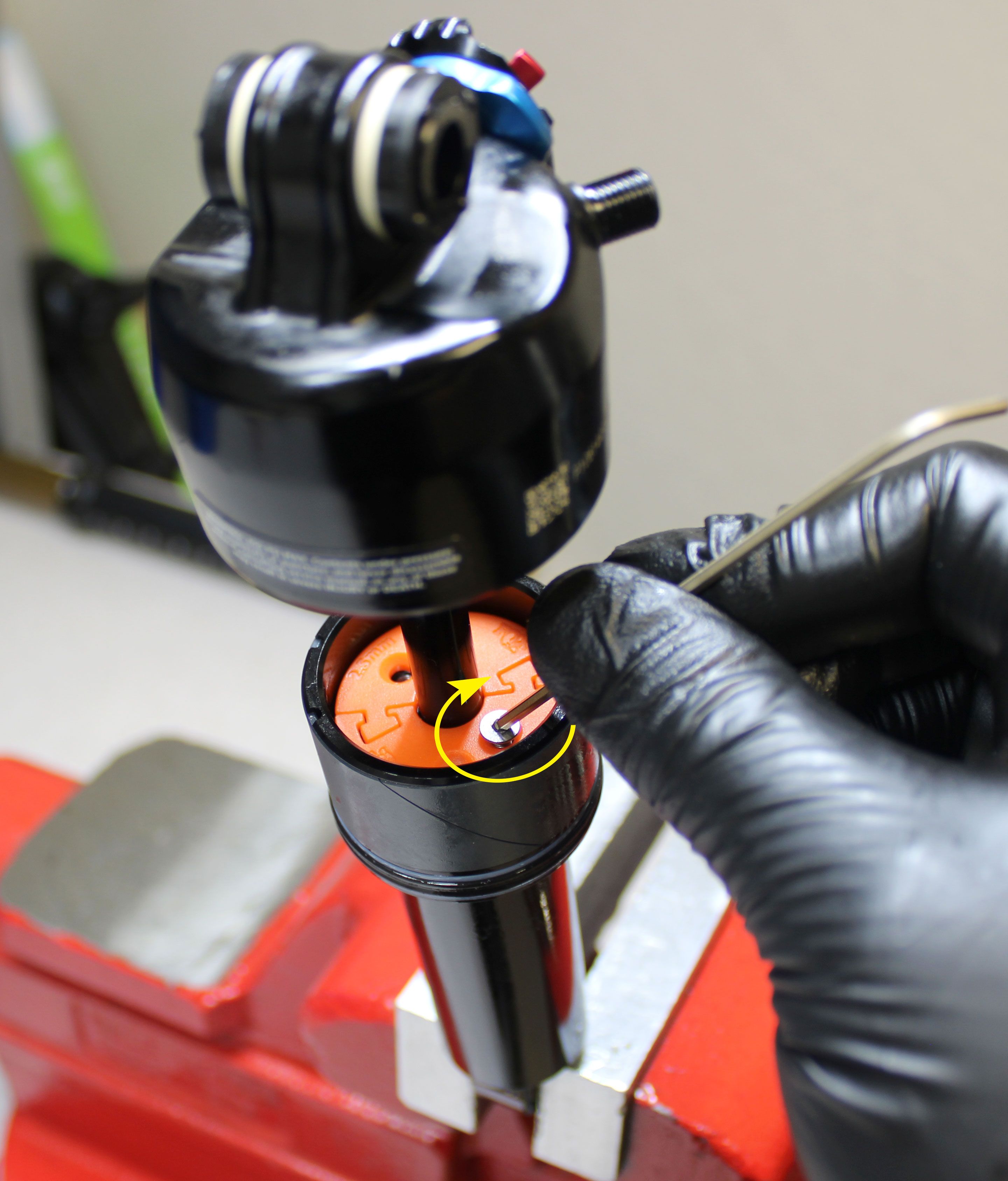
Step 8
Travel Spacers
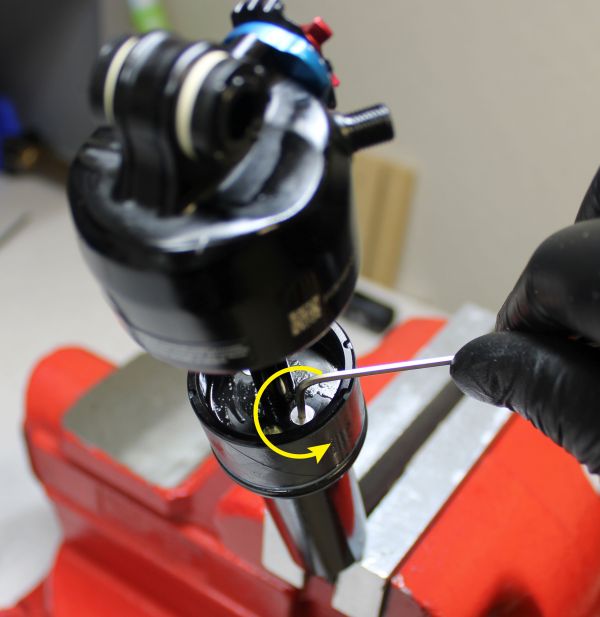
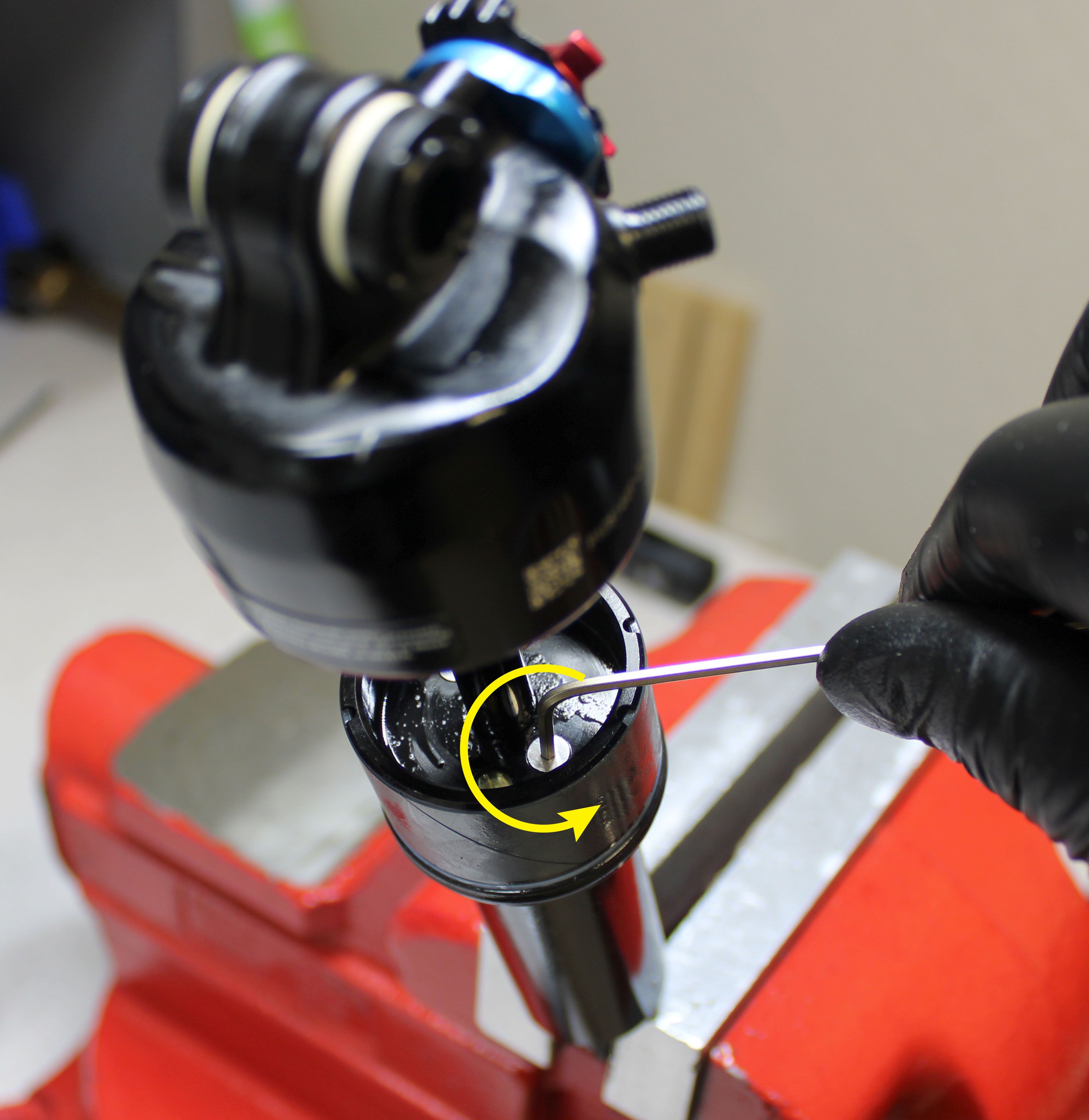
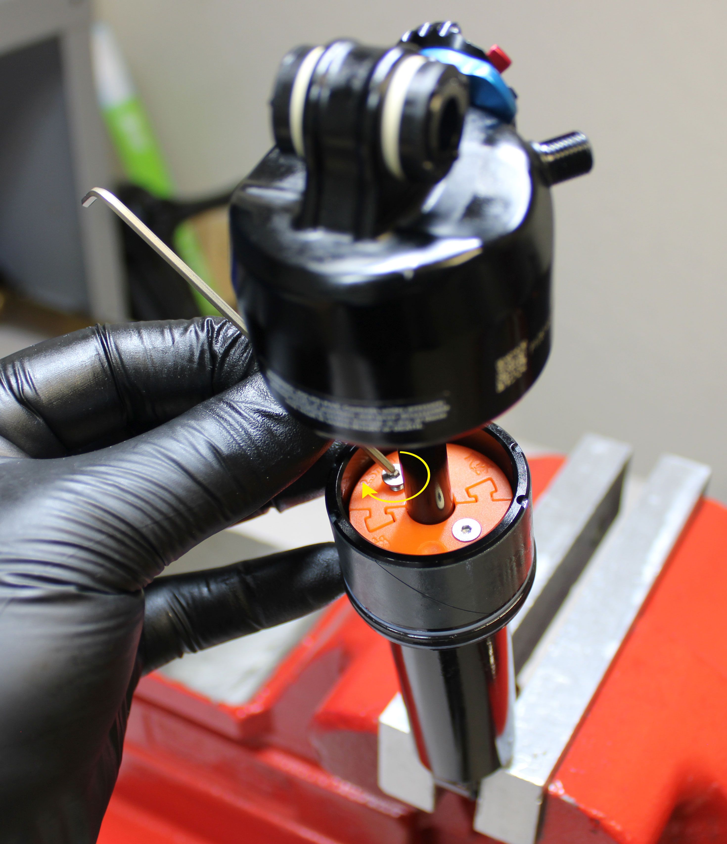
Unthread the two screws in the Bearing Housing Cap counter-clockwise with a 2mm hex wrench.
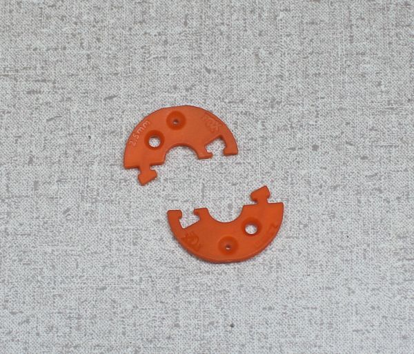
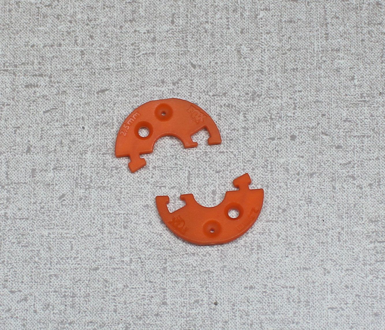
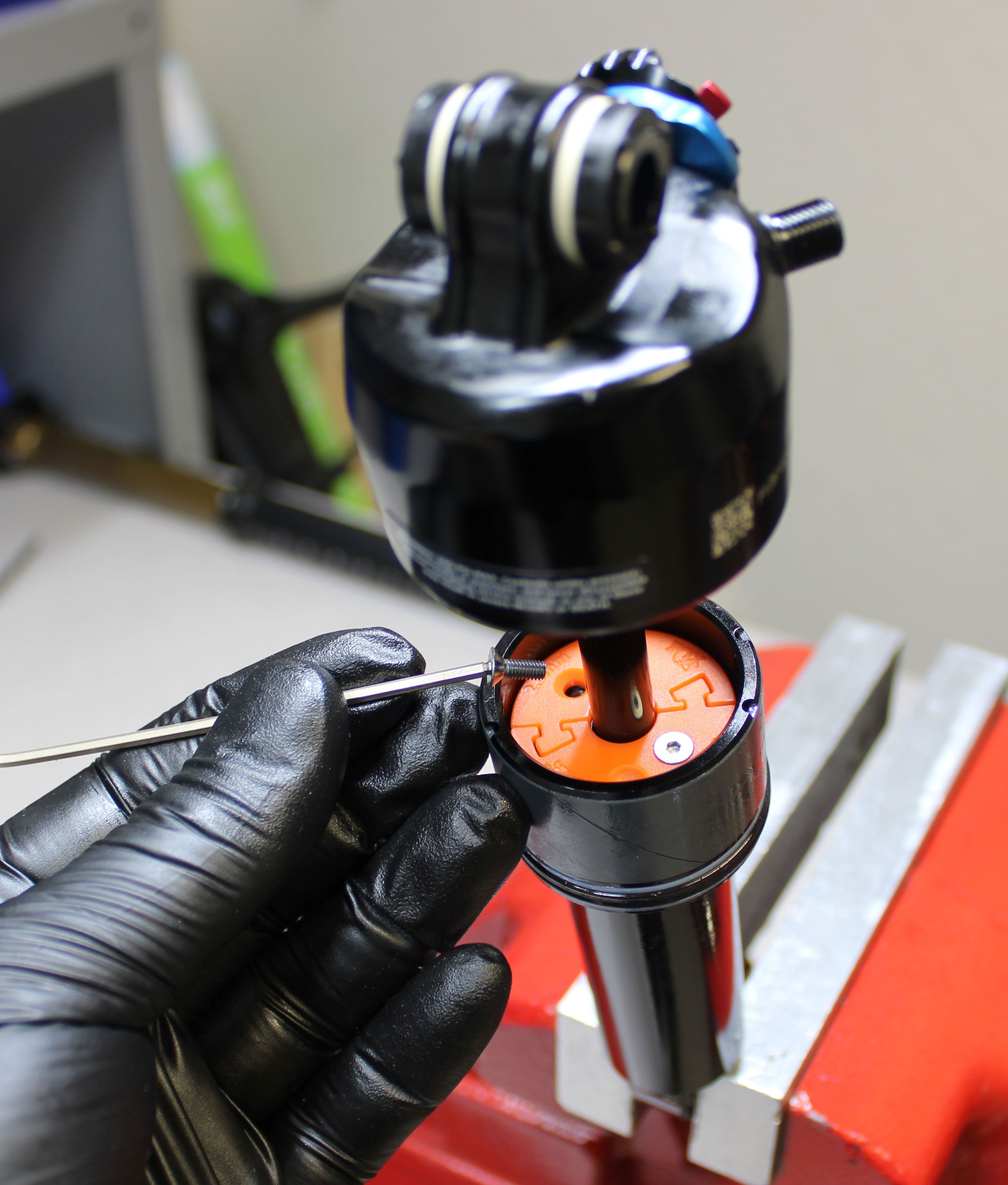
Step 9
Travel Spacers
Travel spacers must be installed in pairs. Engage the two travel spacers with each other once positioned around the shaft. Align the through holes of the spacers with the threaded holes of the bearing housing assembly. Make sure that the FOX logo is visible when the spacers are installed.
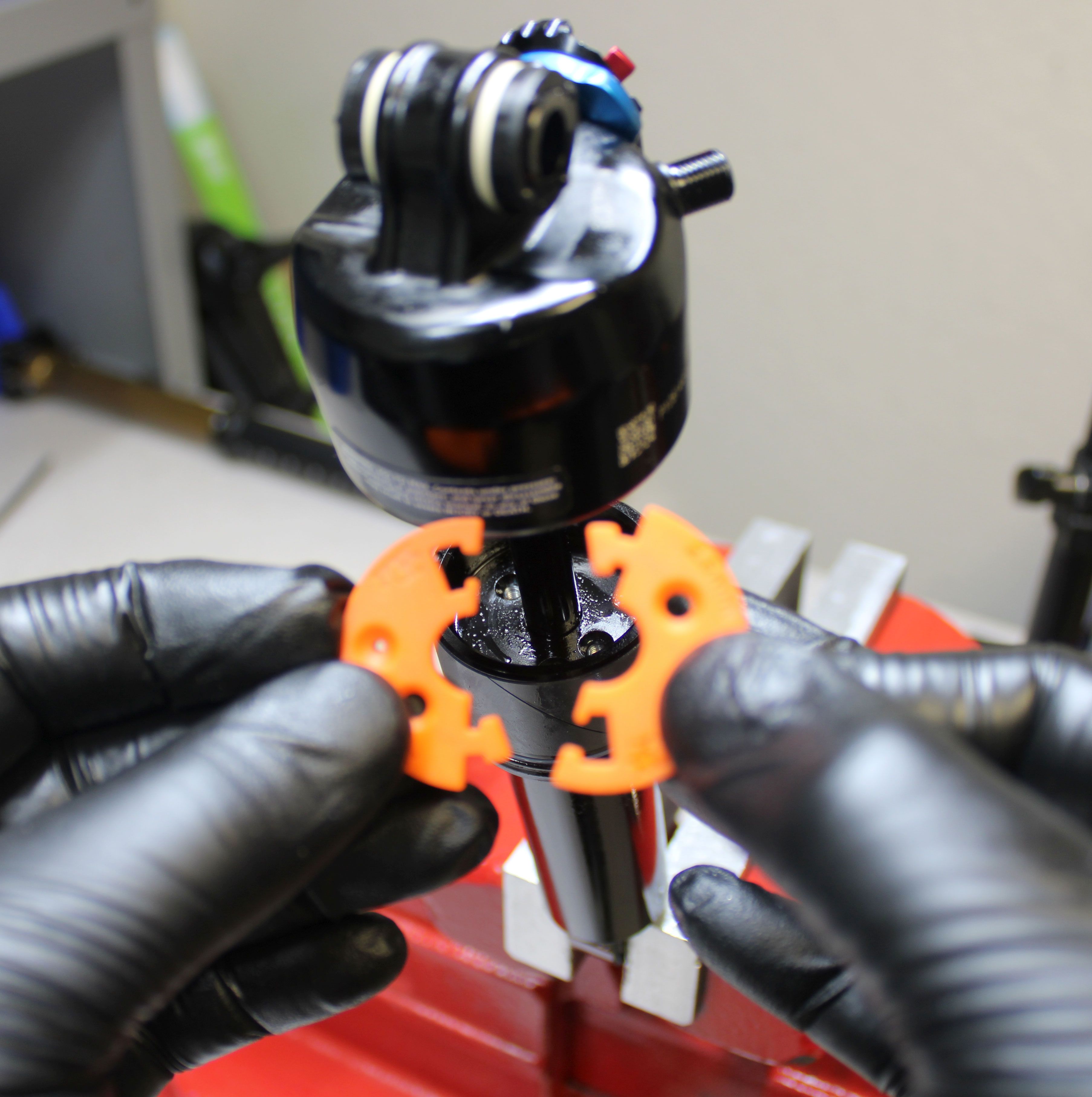

Step 10
Travel Spacers
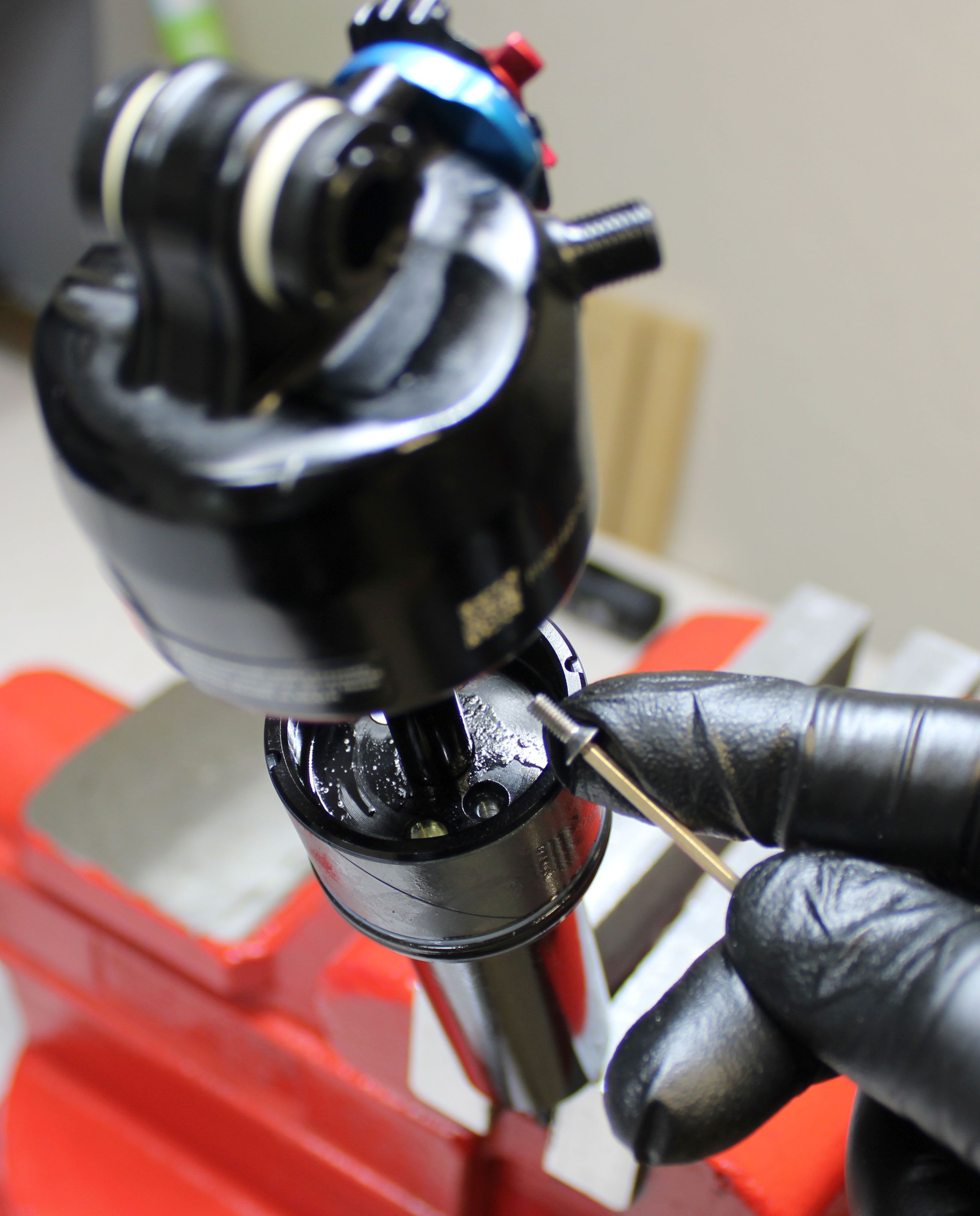
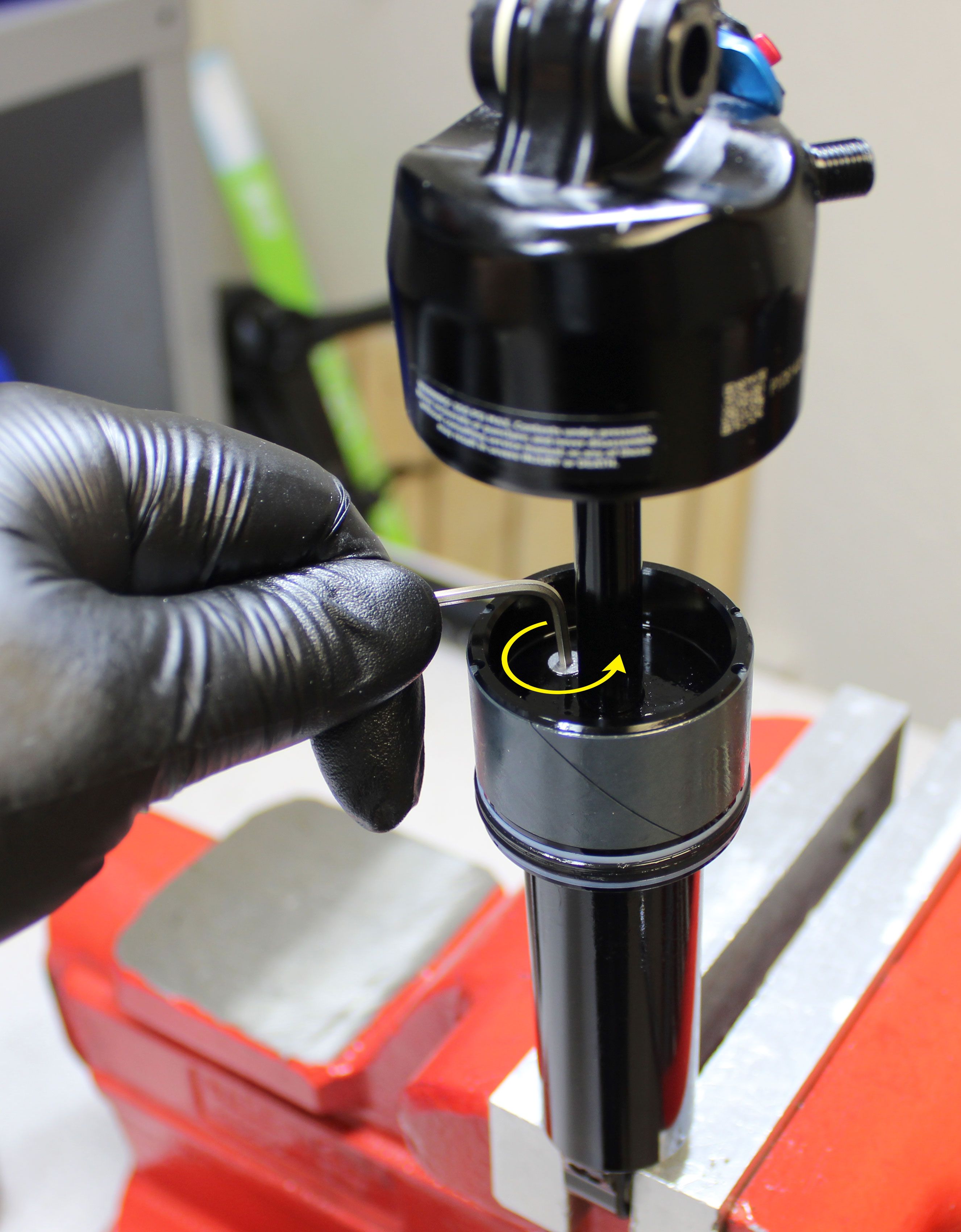
If adding 1 set of 2.5mm travel spacers, reinstall the original shorter length screws. Install the longer screws from the kit when using a total of 2 sets of travel spacers for a 5mm travel reduction. Tighten clockwise to 10 in-lb (1.1 Nm) torque.

Step 11
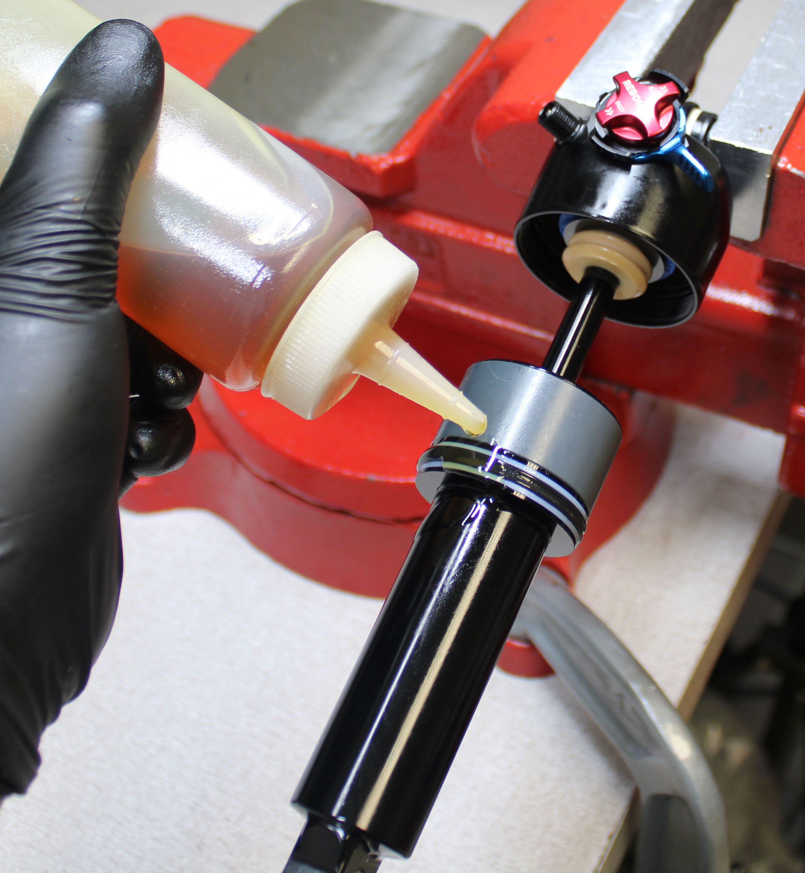
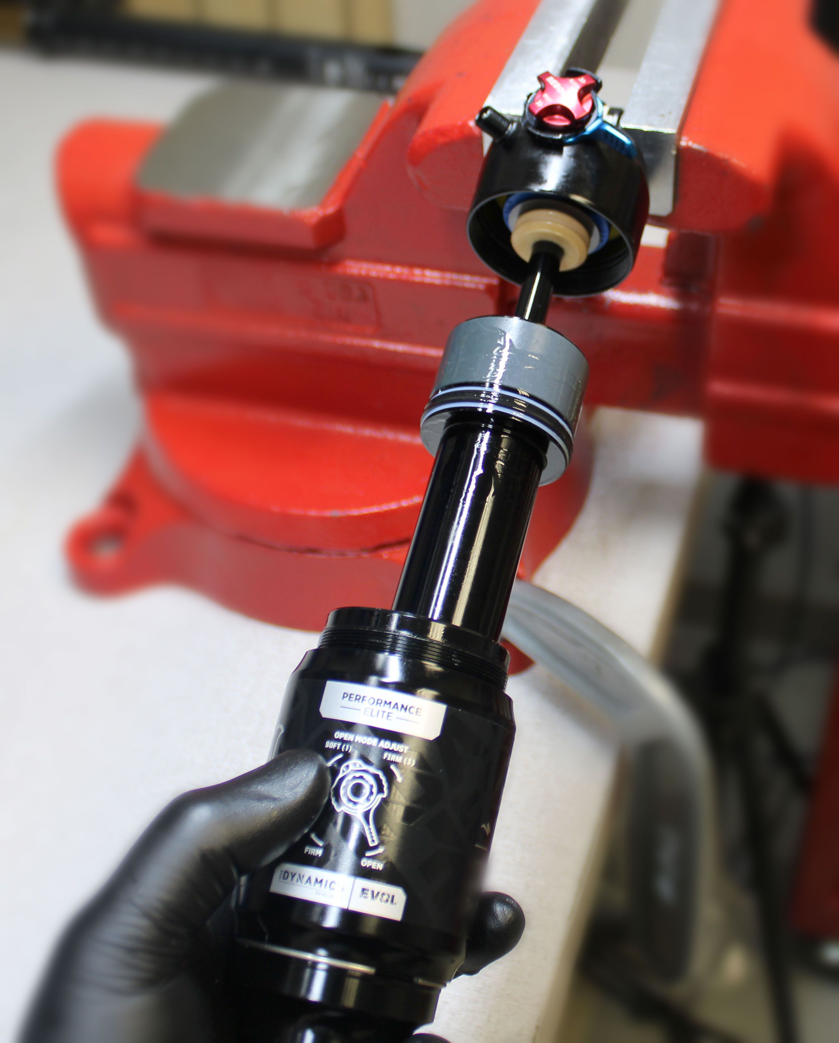
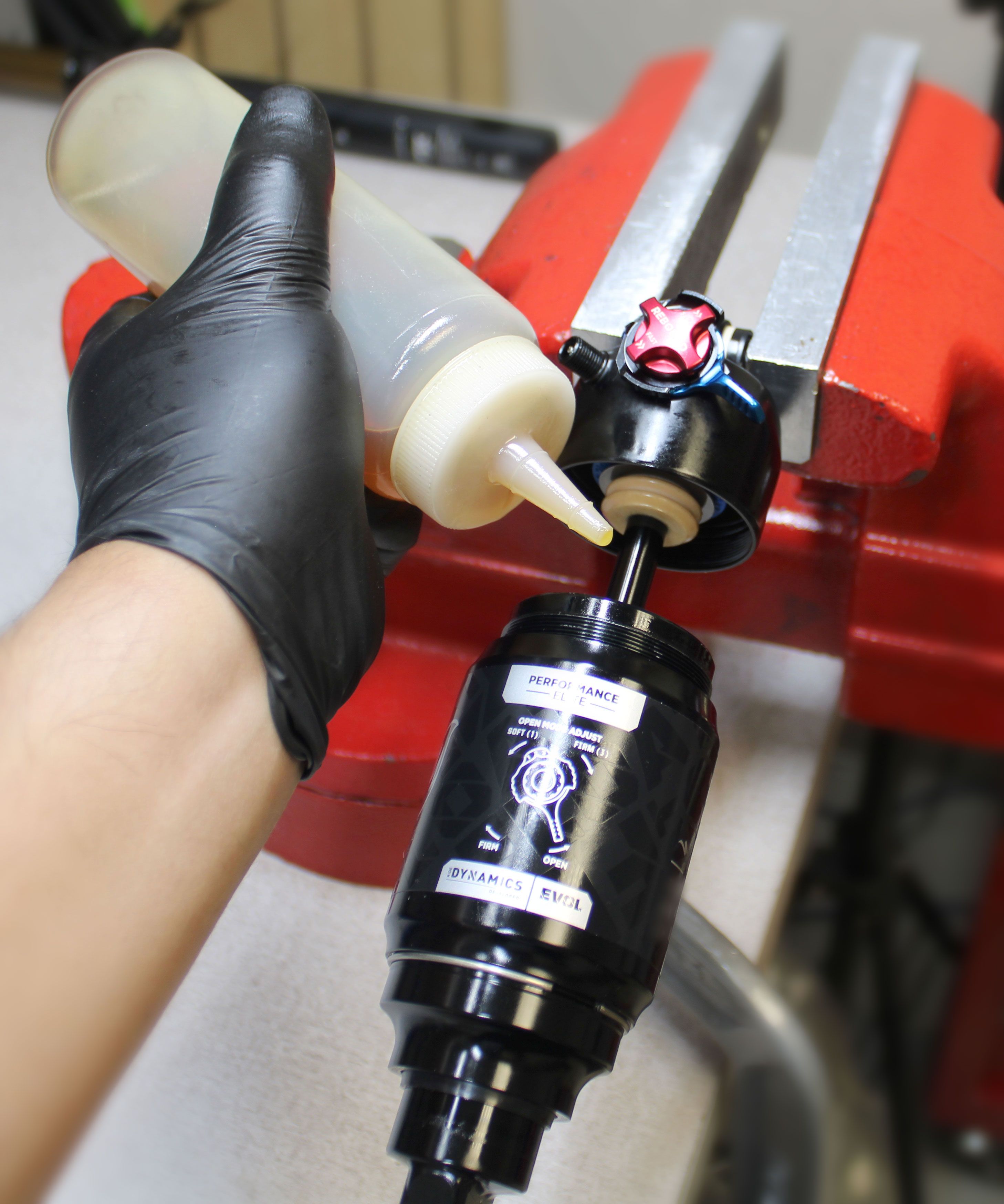
Coat the main air seals with a thin film of FOX 20wt. Gold oil. Start installing the air sleeve onto the shock, then add 2cc of FOX 20wt. Gold oil into the main air chamber as shown. Slide the air sleeve up against the eyelet then thread it clockwise until hand-tight. If mounted on the bike, you may compress the bike's suspension if needed to help slide the air sleeve into the eyelet. Slide the sag indicator o-ring back onto the body.
Step 12
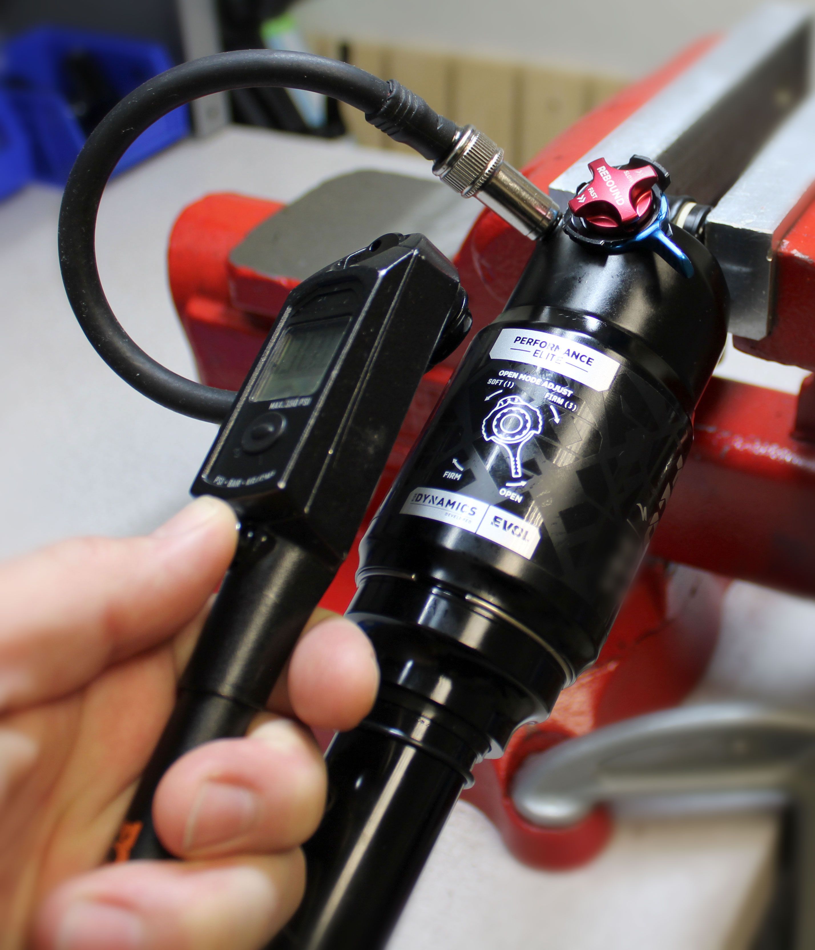
Attach your shock pump then add air while you slowly cycle your shock through 25% of its travel 10 times as you reach your desired pressure. Reinstall the black air cap.